Thermal-error real-time compensation system for high-speed precise machining and compensation method thereof

A real-time compensation and precision machining technology, applied in general control systems, control/regulation systems, instruments, etc., can solve problems such as the reduction of machining accuracy, and achieve fast and high-precision compensation effects and good online monitoring functions.

Inactive Publication Date: 2011-07-13
SHANGHAI JIAO TONG UNIV
View PDF2 Cites 67 Cited by
  • Summary
  • Abstract
  • Description
  • Claims
  • Application Information

AI Technical Summary

Problems solved by technology

However, the above models are usually used for thermal error compensation in medium-sized or large-scale processing machine tools, and have not been studied for high-speed precision machining processes. Due to the different hardware structures, the distribution of the temperature field and thermal performance of the machine tools will be very different. Directly apply the original compensation model to the high-speed precision machining process, otherwise the inappropriate compensation function will reduce the machining accuracy

Method used


Image

  • Thermal-error real-time compensation system for high-speed precise machining and compensation method thereof
  • Thermal-error real-time compensation system for high-speed precise machining and compensation method thereof
  • Thermal-error real-time compensation system for high-speed precise machining and compensation method thereof

Examples


Embodiment Construction

[0044] The embodiments of the present invention are described in detail below. This embodiment is implemented on the premise of the technical solution of the present invention, and detailed implementation methods and specific operating procedures are provided, but the protection scope of the present invention is not limited to the following implementation example.

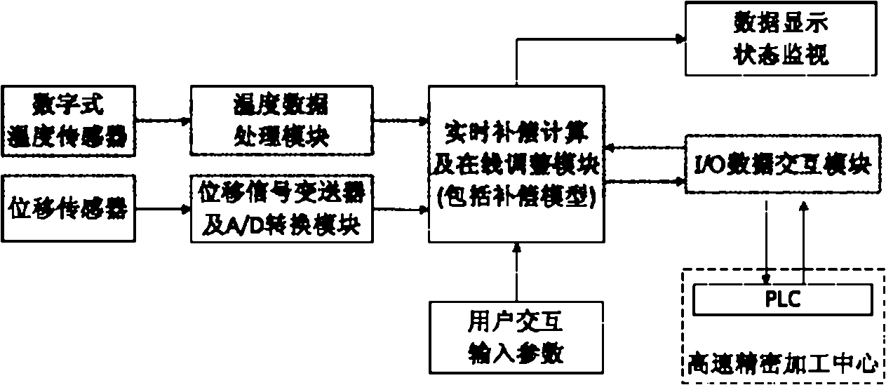
[0045] like figure 1 As shown, the present embodiment includes: digital temperature sensor, temperature data processing module, displacement sensor, displacement signal transmitter and A / D conversion module, real-time compensation calculation and online adjustment module, data display and status monitoring module, I / O O data interaction module and user interaction module, wherein: the digital temperature sensor is connected with the temperature data processing module and transmits the spindle temperature information measured in real time, and the displacement sensor is connected with the displacement signal transmi...


PUM


Abstract

The invention relates to a thermal-error real-time compensation system for high-speed precise machining and a compensation method thereof in the technical field of numerical control machine processing. The system comprises a digital temperature sensor, a temperature data processing module, a displacement sensor, a displacement signal transmitter, an A / D (Analog / Digital) conversion module, a real-time compensation calculation and online adjustment module, a data display and state monitor module, an I / O (Input / Output) data interaction module and a user interaction module. The invention can realize rapid high-accuracy compensation effect and favorable online monitoring.

Description

technical field [0001] The invention relates to a device and method in the technical field of numerical control machine tool processing, in particular to a thermal error real-time compensation system and compensation method for high-speed precision machining. Background technique [0002] Precision and ultra-precision machining technology was formed and developed in the United States in the early 1960s due to the development of aerospace technology and military technology. With the increasing role of precision machining technology in promoting military technology, all countries have focused on funding and researching and developing it as a national key technology. The United States took the lead in promulgating the "Advanced Manufacturing Technology Plan" and "Manufacturing Technology Center Plan", and Germany formulated the "Manufacturing Plan". Japan also paid attention to the basic research of precision machining technology in the 1980s and applied it to the civilian hig...

Claims


Application Information

Patent Timeline
Patent Type & Authority Applications(China)
IPC IPC(8): G05B19/404
Inventor 杨建国张毅姚晓栋张琨沈岳熙
Owner SHANGHAI JIAO TONG UNIV
Why Eureka
Try Eureka