Annular illuminating device
An illuminator and ring-shaped technology, which is applied in the direction of lighting devices, lighting auxiliary devices, lighting and heating equipment, etc., can solve the problems of insufficient illumination of tools, etc., and achieve the goal of preventing uneven illumination, suppressing shaking, and sufficient illumination Effect
- Summary
- Abstract
- Description
- Claims
- Application Information
AI Technical Summary
Problems solved by technology
Method used
Image

Examples
Embodiment 1
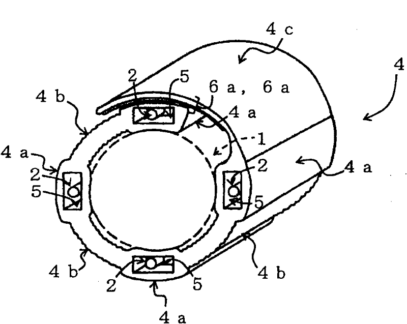
[0037] use figure 1 and figure 2 The first embodiment of the ring illuminator will be described.
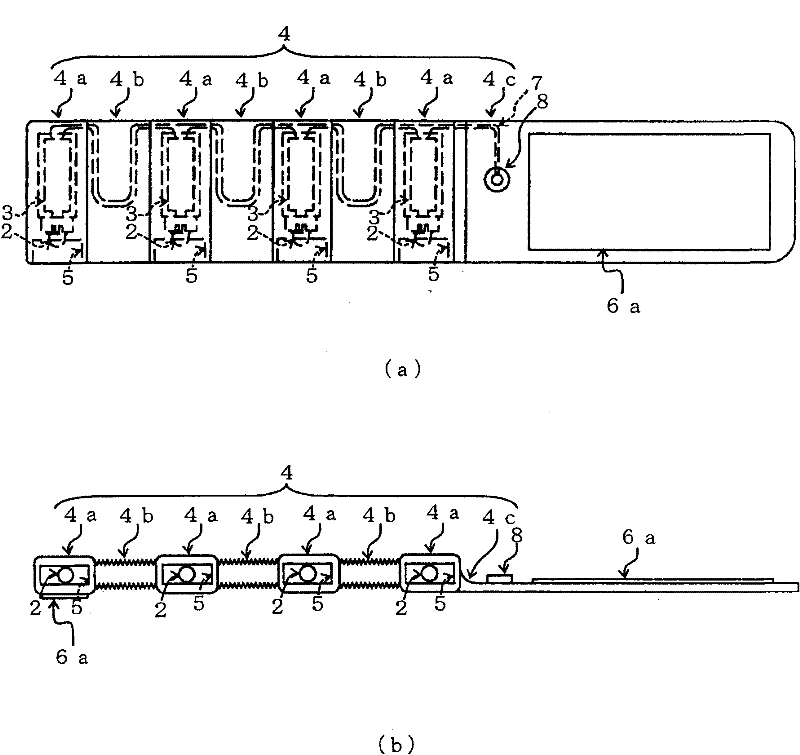
[0038] figure 1 It is an external perspective view of Example 1 of the ring illuminator according to the embodiment of the present invention. figure 2 (a) and (b) are the top view and the front view of the ring illuminator of Embodiment 1, respectively.
[0039] The ring illuminator of the present embodiment is wound around an operator's hand or a side surface of a stick-shaped tool, etc., using a windable mounting unit so that the light emitting part is arranged in a ring shape. Such as figure 1 As shown, the ring illuminator includes four light emitting parts 2 arranged in a ring around the tool 1 , and a mounting belt 4 as a mounting unit for mounting the light emitting parts 2 to the tool 1 .
[0040] The attachment belt 4 is alternately provided with the accommodation part 4a and the connection part 4b in the longitudinal direction. In the storage part 4a, the recess...
Embodiment 2
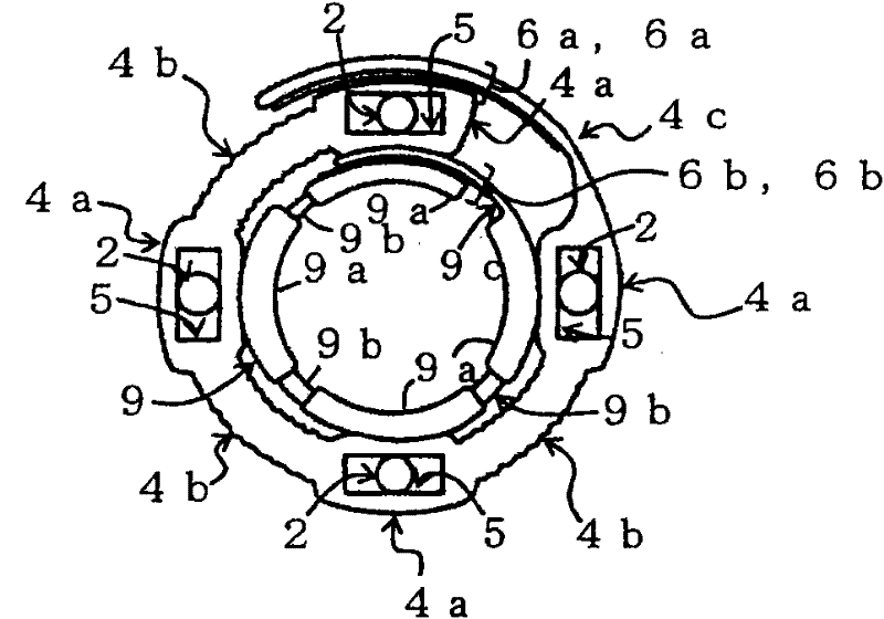
[0049] image 3 It is the front view of the ring illuminator of the second embodiment. Figure 4 (a) and (b) are respectively a plan view and a front view of the auxiliary belt constituting the ring illuminator of the second embodiment. about figure 1 or figure 2 Components shown in , are denoted by the same reference numerals and their descriptions are omitted.
[0050] Such as image 3 As shown, the ring illuminator of this embodiment is characterized in that: compared with the first embodiment, it further includes an auxiliary belt 9 . That is, in the ring illuminator of the first embodiment, the mounting tape 4 is directly wound around the rod-shaped tool or the like, but in the ring illuminator of the present embodiment, the auxiliary tape 9 is first wound around the rod-shaped tool or the like, and then The attachment tape 4 is wound around the auxiliary tape 9 .
[0051] The auxiliary belt 9 is alternately provided with supporting parts 9a and connecting parts 9b...
Embodiment 3
[0057] use Figure 5 ~ Figure 7 The third embodiment of the ring illuminator (especially corresponding to the first aspect and the second aspect of the present invention) will be described.
[0058] Figure 5 It is an external perspective view of Example 3 of the ring illuminator according to the embodiment of the present invention. Figure 6 It is an external view of the ring illuminator of Example 3 viewed from the mounting surface side. Figure 7 (a) is a plan view showing a modified example of the ring illuminator of Embodiment 3, and (b) and (c) are X-X line sectional views and Y-Y line sectional views of (a), respectively. about figure 1 or figure 2 Components shown in , are denoted by the same reference numerals and their descriptions are omitted. In addition, in Figure 7 (a) omits the illustration of the suspenders, in Figure 7 In (c), hatching of the light emitting part 2 is omitted. Figure 7 (b) shows a state where the ON-OFF switch is pressed.
[0059] ...
PUM
 Abstract
Description
Claims
Application Information
 - R&D Engineer
- R&D Manager
- IP Professional
- Industry Leading Data Capabilities
- Powerful AI technology
- Patent DNA Extraction
Browse by: Latest US Patents, China's latest patents, Technical Efficacy Thesaurus, Application Domain, Technology Topic.
© 2024 PatSnap. All rights reserved.Legal|Privacy policy|Modern Slavery Act Transparency Statement|Sitemap