Terminal fitting and connector provided therewith

a technology of fittings and connectors, applied in the direction of securing/insulating coupling contact members, coupling device connections, electrical devices, etc., can solve the problem of not being able to form the retracted portion over the entire width of the rectangular tube including the thickness range of the side plates, and achieve the effect of large engagement margin and stabilizing the tube postur

Active Publication Date: 2013-03-14
SUMITOMO WIRING SYST LTD
View PDF2 Cites 10 Cited by
  • Summary
  • Abstract
  • Description
  • Claims
  • Application Information

AI Technical Summary

Benefits of technology

[0009]The locking hole preferably extends over the entire width of the lid plate. The retracted portion also preferably is formed over the entire width. Additionally, the front and the rear plates of the lid plate portion preferably are cantilevered from the side plate independently of each other. Thus, the position of a fold line along which the rear plate and the side plate are connected at a substantially right angle can be set at a position displaced inward of the rectangular tube from the position of a fold line along which the front plate and the side plate are connected at a substantially right angle, and the height difference can be provided between the front and the rear plates. The rear plate is cantilevered and hence can extend over the entire width of the rectangular tube if an exte

Problems solved by technology

That is, it is structurally impossible to form the retracted portion over the entir

Method used


Image

  • Terminal fitting and connector provided therewith
  • Terminal fitting and connector provided therewith
  • Terminal fitting and connector provided therewith

Examples


Embodiment Construction

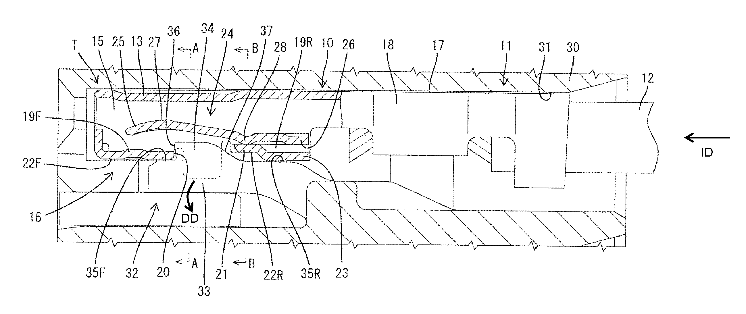
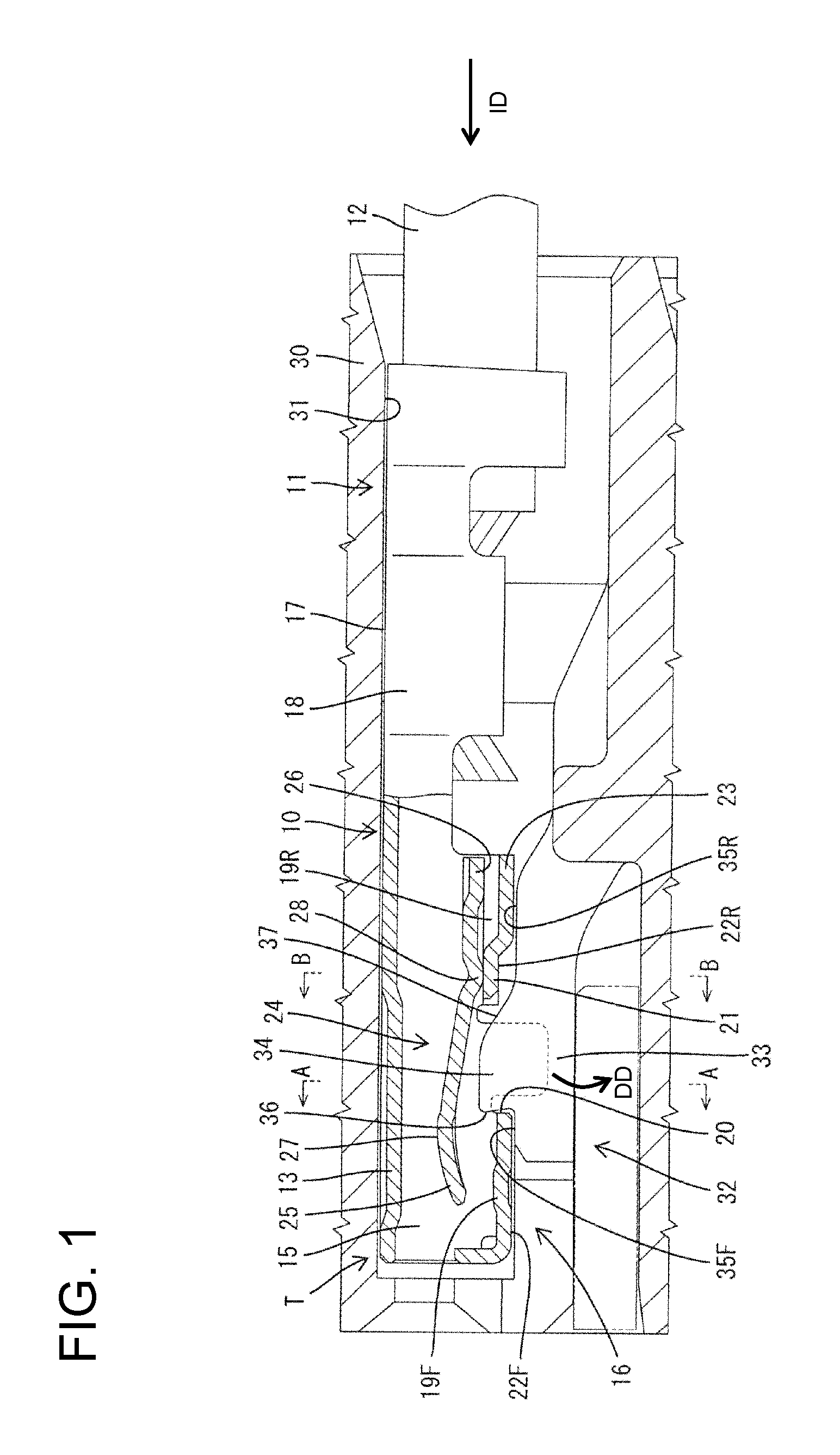
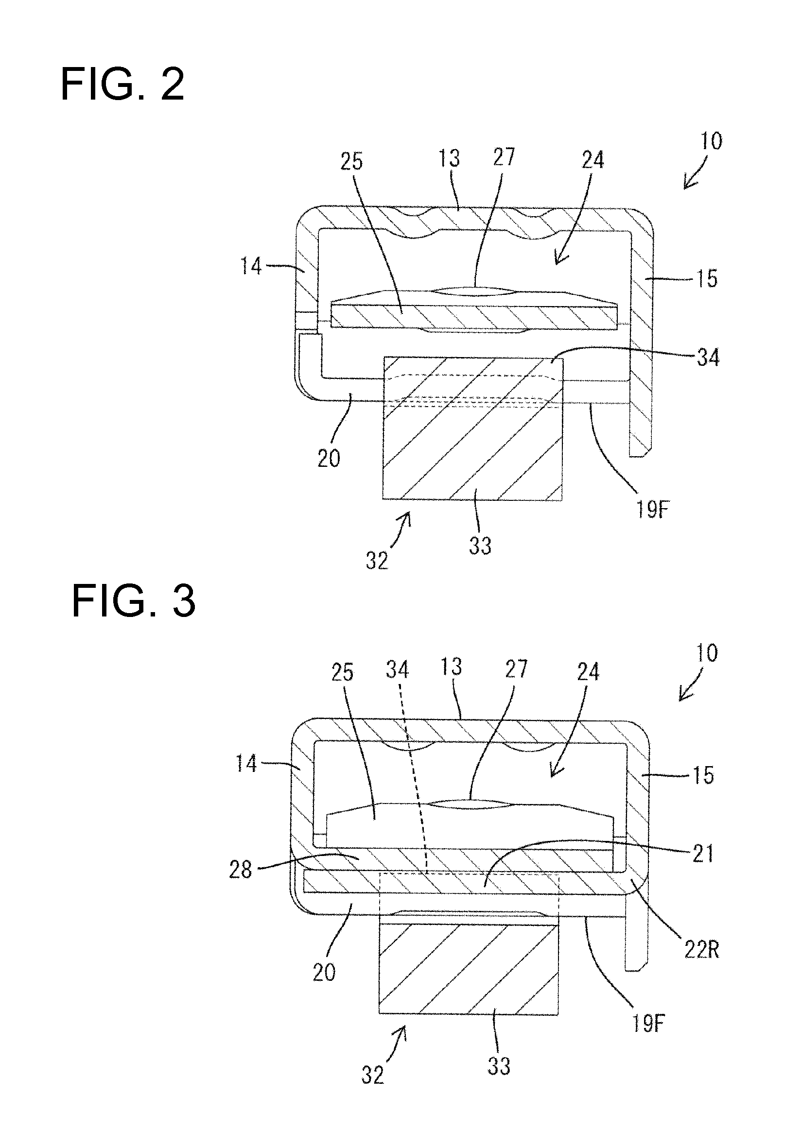
[0024]A terminal fitting in accordance with the invention is identified by the letter T in FIGS. 1, 5 to 7. The terminal fitting T is a female terminal formed with a substantially rectangular tube 10 at a front and a wire crimping portion 11 at a rear end. A front part of a wire 12 is to be connected to the wire crimping portion 11. As shown in FIG. 1, the terminal fitting T is to be inserted from behind into a terminal accommodating chamber 31 formed in a housing 30. In the following, a connection side of the terminal fitting T with a mating terminal fitting (not shown) is referred to as the front.

[0025]A locking lance 32 is cantilevered forward from a lower wall of the terminal accommodating chamber 31 and is configured for holding and retaining the terminal fitting T that has been inserted properly inserted into the terminal accommodating chamber 31. The locking lance 32 has a main body 33 that is resiliently deformable to retract out and down. A locking projection 34 projects up...


PUM


Abstract

A rectangular tube (10) of a terminal fitting (T) includes a lid plate (16) extending substantially at a right angle from the extending end of a right side plate (15) and formed with a locking hole (20) extending over the entire width. A front plate (19F) is cantilevered from the right side plate (15) and arranged before the locking hole (20). A rear plate (19R) is cantilevered from the right side plate independently of the front plate (19F) and is behind and adjacent to the locking hole (20). A retracted portion (21) is formed over the entire width at the rear plate (19R), retracted inwardly of the rectangular tube (10) from the front plate (19F) to provide a height difference within the range of an engagement margin with a locking projection (34) and capable of facing a rear end of the locking projection (34).

Description

BACKGROUND OF THE INVENTION[0001]1. Field of the Invention[0002]The invention relates to a terminal fitting and to a connector provided therewith.[0003]2. Description of the Related Art[0004]U.S. Pat. No. 7,374,465 discloses a female terminal fitting with a rectangular tube at a front end and a wire crimping portion in the form of an open barrel at a rear end. The wire crimping portion defines an open barrel with a bottom wall and two side plates extending from left and right sides of the bottom wall. The rectangular tube has a base plate connected to the bottom wall of the wire crimping portion, two side plates extending at substantially right angles from left and right sides of the base plate and a lid plate extending at a substantially right angle from the end of at least one side plate opposite the base plate. The base plate is formed with a locking hole. The terminal fitting inserted into a terminal accommodating chamber of a housing from behind and a locking projection of a lo...

Claims


Application Information

Patent Timeline
IPC IPC(8): H01R13/42
CPCH01R13/113H01R13/4364H01R13/4223
Inventor HIRABAYASHI, OSAMUOKAMOTO, MICHIAKINORO, YUTAKAHIRASAWA, DAISUKEMIZUTANI, YOSHIHIRO
Owner SUMITOMO WIRING SYST LTD
Why Eureka
Try Eureka