Floor reaction detector of legged mobile robot

Inactive Publication Date: 2010-07-13
HONDA MOTOR CO LTD
View PDF36 Cites 7 Cited by
  • Summary
  • Abstract
  • Description
  • Claims
  • Application Information

AI Technical Summary

Benefits of technology

[0030]Since an insulator is disposed around the floor reaction force detector, the detector can be prot

Problems solved by technology

Therefore, the heel is likely to deteriorate and as a result, the impact-absorbing effect at foot landing decreases in the course of time.
This may degrade posture stability and detection accuracy of the floor reaction force.
However, if the feet are configured

Method used


Image

  • Floor reaction detector of legged mobile robot
  • Floor reaction detector of legged mobile robot
  • Floor reaction detector of legged mobile robot

Examples


Example

[0079]Since the rest of the structure is the same as that of the first embodiment, no further explanation will be made.

[0080]Next, a floor reaction force detector of a legged mobile robot according to a third embodiment will be explained with reference to FIG. 8.

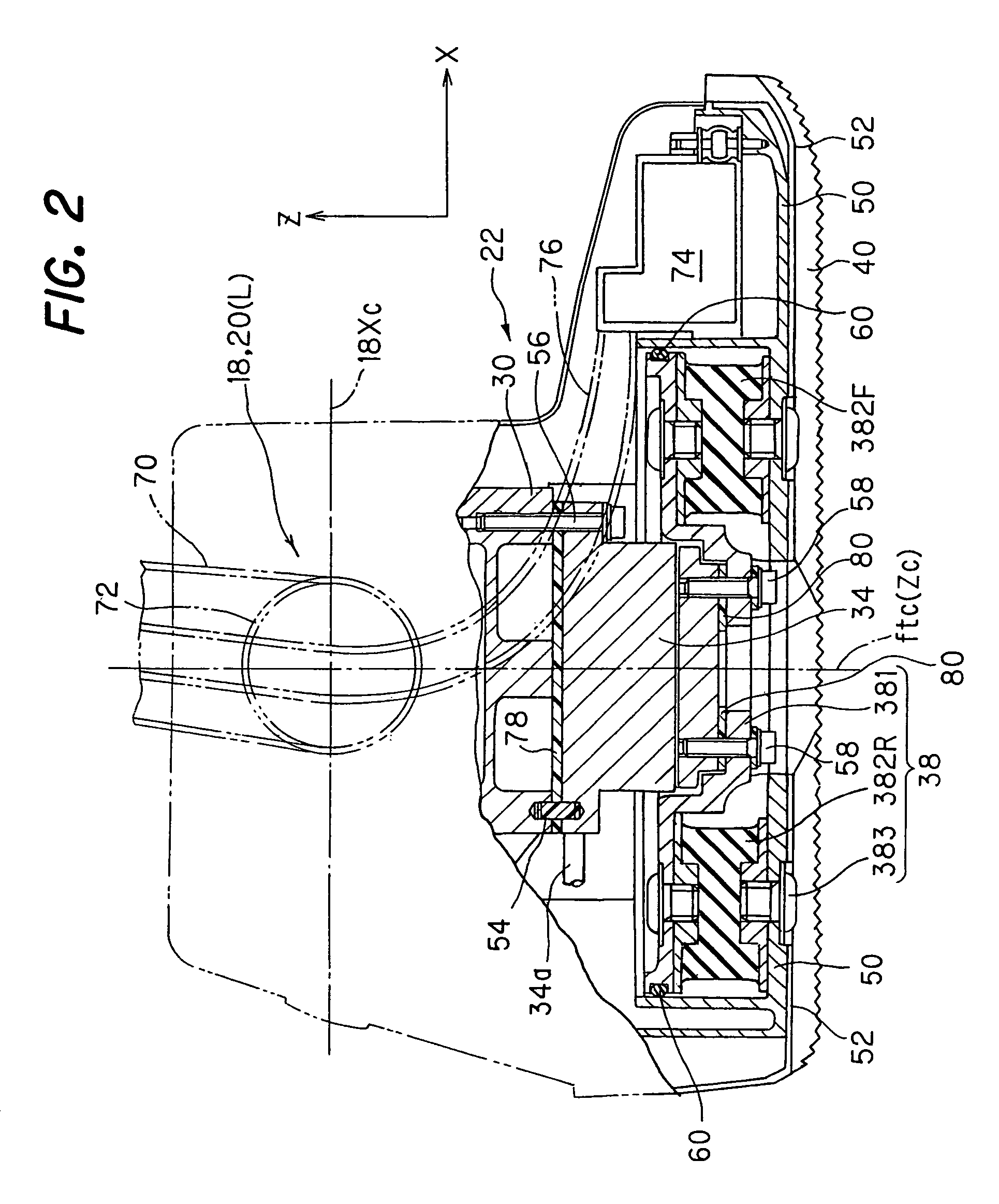
[0081]FIG. 8 is a view, similar to FIG. 3, but showing the left foot 22L of the feet 22R, 22L for explaining the floor reaction force detector of a legged mobile robot according to the third embodiment.

Example

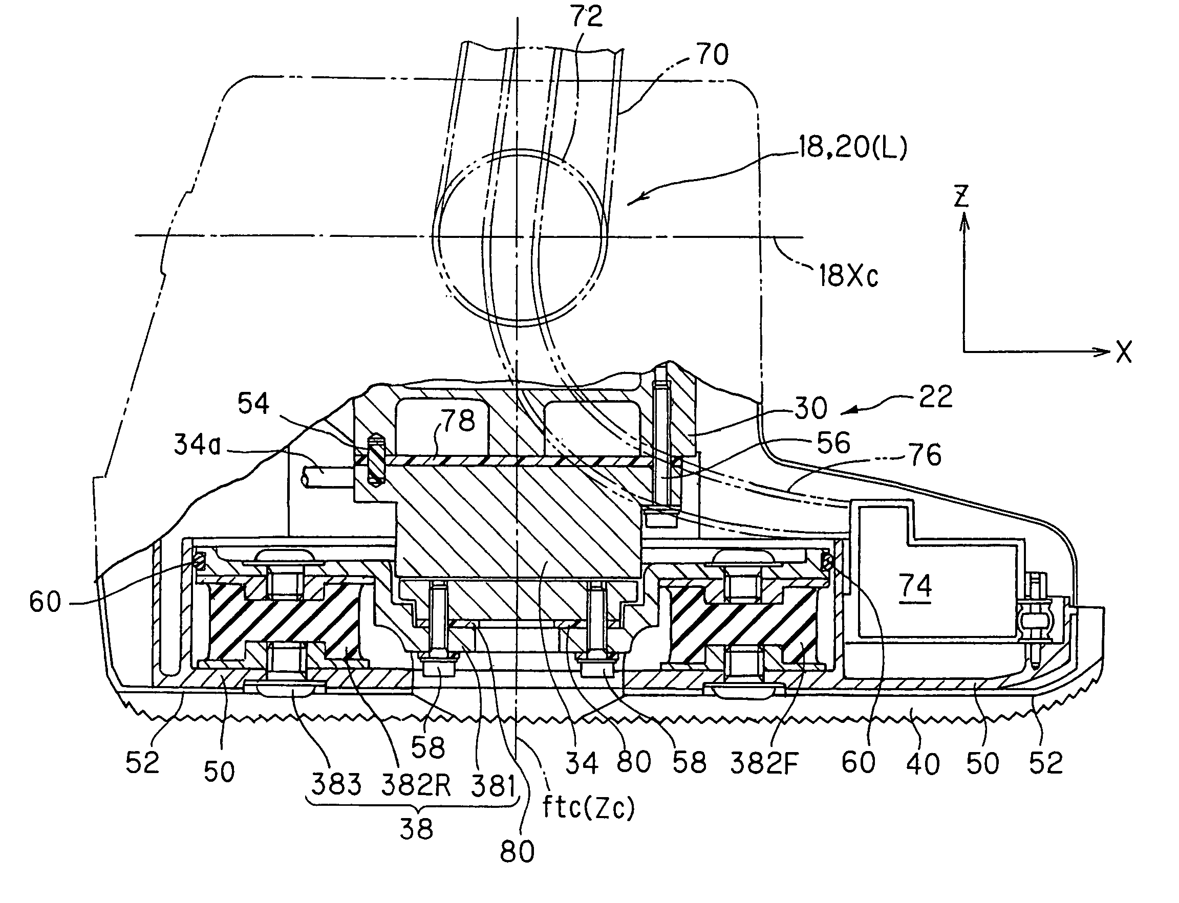
[0082]In the third embodiment, the six-axis force sensor 34 is installed in such a manner that the sensitivity center line Zc thereof is positioned at the center of gravity or center of mass of a triangle (more precisely a regular triangle with three equally angled vertexes), formed by the three bush-like rubber members 382 (382F, Ra, Rb). With this, it becomes possible to improve the posture stability and to improve detection accuracy.

[0083]Further, in this embodiment, rigidity of the bush-like rubber member Rb is made higher than that of the member 382F, and the bush-like member 382Ra is made still higher than that of the member 382Rb. Thus, the rigidity of the heel and thereabout and the outer foot portion 22a is improved and the impact-absorbing effect is accordingly prevented from decreasing in the course of time, thereby enabling to avoid the degradation of the posture stability and floor reaction force detection accuracy.

[0084]Since the rest of the structure is the same as th...


PUM


Abstract

In a legged mobile robot having at least a body and a plurality of legs each connected to the body through a first joint and a foot each connected to a distal end of each of the legs through a second joint, a floor reaction force detector is installed between the second joint and a contact end of the foot. More specifically, an upper portion of the floor reaction force detector is connected at a location near the second joint, and the contact end of the foot or thereabout is constituted by a spring mechanism that is lower in rigidity than a member constituting the second joint or thereabout such that a lower portion of the floor reaction force detector is connected to the contact end through the spring mechanism. With this, it becomes possible to provide the floor reaction force detector that can improve detection accuracy of the floor reaction force and prevent the performance of control from being degraded, while enabling to maintain a stable posture during standing and to decrease the impact at foot landing.

Description

TECHNICAL FIELD TO WHICH THE INVENTION RELATES TO[0001]This invention relates to a floor reaction force detector of a legged mobile robot.BACKGROUND ART OF THE INVENTION[0002]In legged mobile robots, in particular, in biped mobile robots, the floor reaction force detector such as a six-axis force sensor is used to detect the floor reaction force acting on the robot from a floor surface which the robot contacts and based on the detect a floor reaction force, control is appropriately conducted to achieve stable walking. In order to improve detection accuracy, the floor reaction force detector should preferably be installed at a position close to a floor contact end of the feet. In view of this, a technique mentioned in Japanese Laid-Open Patent Application No. 2000-254888 proposes to install the floor reaction force detector at the sole of foot such that the floor reaction force detector contacts a floor surface directly.[0003]However, in this prior art, since the floor reaction force...

Claims


Application Information

Patent Timeline
IPC IPC(8): G06F19/00G01L5/16B25J5/00B25J13/08B25J19/00B25J19/02B62D57/032
CPCB25J13/085B25J19/0091B62D57/032B25J5/00
Inventor HIROSE, MASATOGOMI, HIROSHI
Owner HONDA MOTOR CO LTD
Why Eureka
Try Eureka