Self-service cabinet

A cabinet and self-service technology, applied in computer parts, instruments, induction record carriers, etc., can solve the problems of high threshold, increased difficulty for hardware manufacturers, high complexity, etc., to reduce costs, provide reliability and scalability Effect

Inactive Publication Date: 2011-07-20
TRAVELSKY
View PDF3 Cites 1 Cited by
  • Summary
  • Abstract
  • Description
  • Claims
  • Application Information

AI Technical Summary

Benefits of technology

This patented technology allows users without having access to their own equipment (such as displays or screens) but still have control over them by providing an independent system called Self Service KIOSKs. They don't require any feedback about what they are doing on those platforms like traditional kiosms. Instead, this means there won’t be issues where multiple servers may want different things at once - just one thing being done instead of another altogether.

Problems solved by technology

Technological Problem: Current methods used at home service counters involve complex software interfaces with many different types of equipment being connected through various means like cables or wireless networks. These connections require significant effort from IT staff members working alongside them. Additionally, these systems have limited flexibility due to their fixed infrastructure design. Therefore, technical problem addressed in this patented solution involves ensuring stability while providing an efficient method for adding new features into existing machines without requiring extensive modifications.

Method used


Image

  • Self-service cabinet
  • Self-service cabinet

Examples


Embodiment Construction

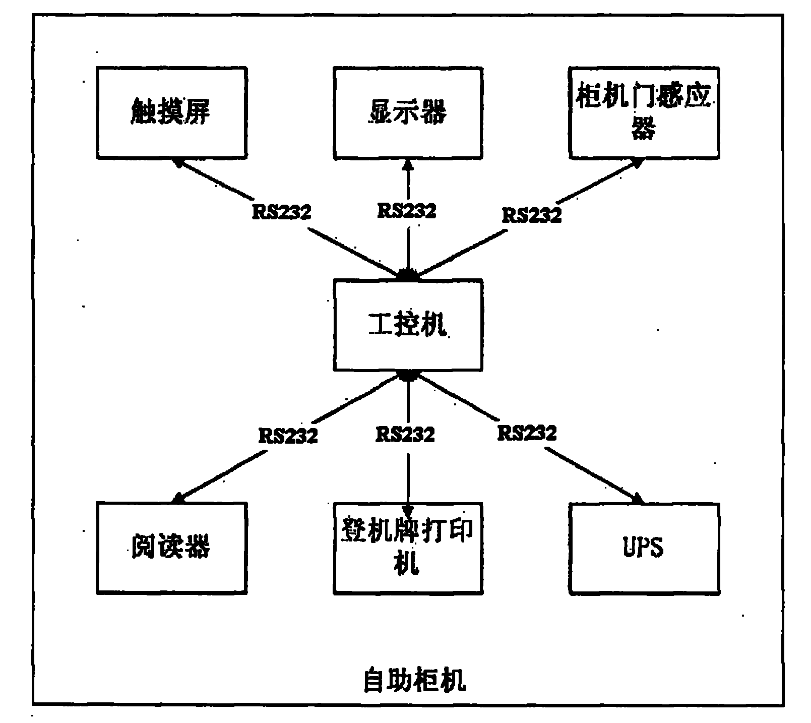
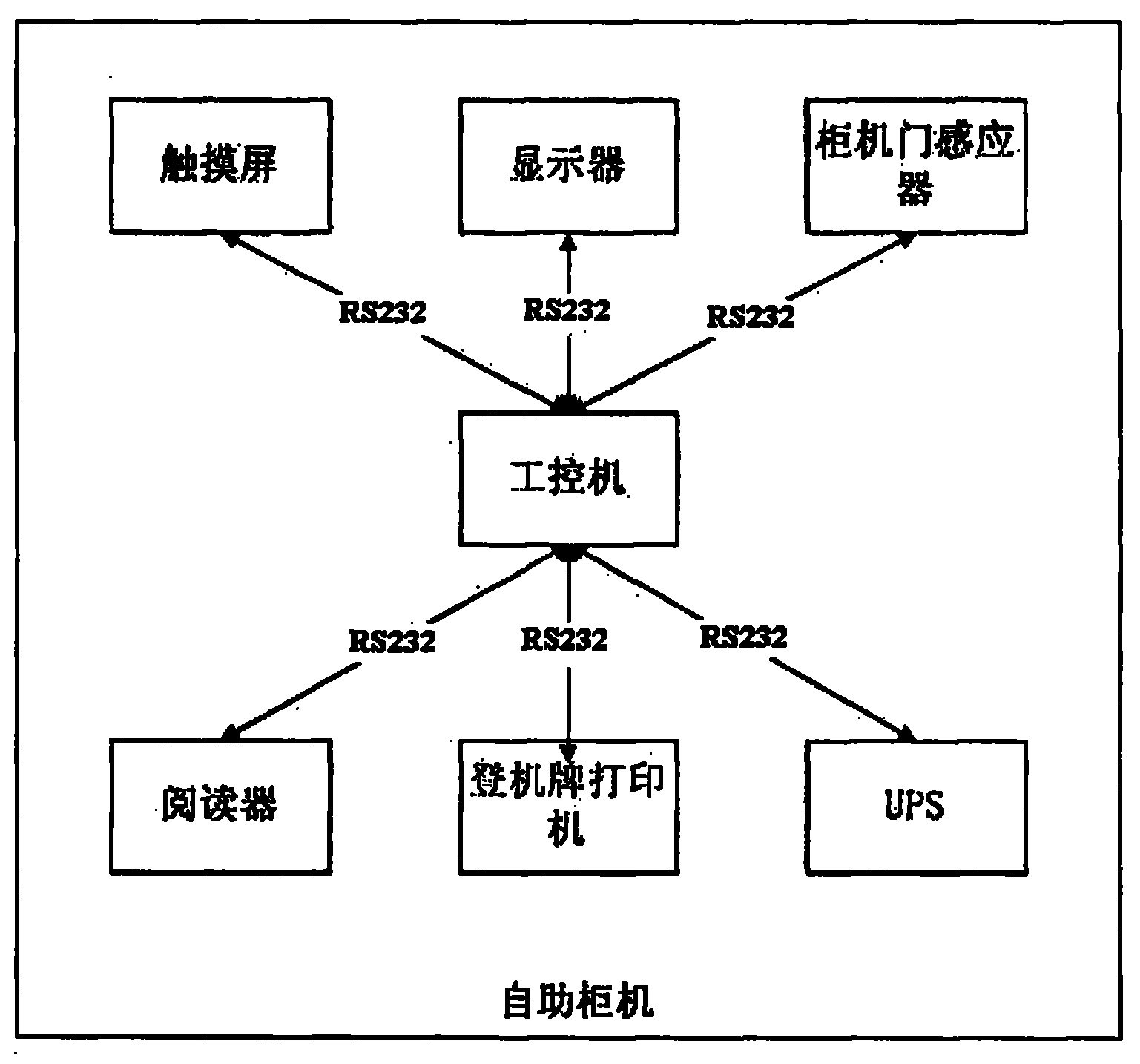
[0035] The self-service cabinet machine of the present invention will be specifically described below with reference to the accompanying drawings. Such as figure 1 As shown, the self-service cabinet machine of the present invention includes a touch screen, a display, a boarding pass printer, a reader, a UPS, and a sensor. The readers include passport readers, magnetic card readers, and barcode readers. The sensors include upper and lower cabinet door sensors, boarding pass number sensors, and the like.

[0036] According to the self-service kiosk machine of the present invention, wherein the boarding pass printer complies with the AEA (Association of European Airlines, European Aviation Federation) standard, we have made some extensions on the AEA standard for the self-service kiosk machine, requiring all feedback to be preceded by adding Prefix "CHECK", if the boarding pass is successfully printed, the AEA standard is PROK, and the standard of TravelSky should be CHECKPROK,...


PUM


Abstract

The invention relates to a self-service cabinet which comprises an industrial personal computer, a touch screen, a display device, a boarding check printer, a reader, a UPS (Uninterruptable Power System) and an inductor and is characterized in that the reader comprises a passport reader, a magnetic card reader and a bar code reader; and the inductor comprises an upper and lower cabinet door inductor and a boarding check quantity inductor.

Description


Claims


Application Information

Patent Timeline
Owner TRAVELSKY
Why Eureka
Try Eureka