
A modified process for hydrocarbon recovery using in situ combustion

A hydrocarbon, oxidizing technology that can be used in earthmoving, wellbore/well components, and production fluids to solve problems such as increased cost and increased environmental "footprint impact"

Inactive Publication Date: 2014-05-07
ARCHON TECH LTD
View PDF8 Cites 0 Cited by
  • Summary
  • Abstract
  • Description
  • Claims
  • Application Information

AI Technical Summary

Problems solved by technology

This requires open access through clearcutting at the injection well location and / or requires increased space to accommodate additional oxidizing gas delivery and / or generation and compression facilities, thereby increasing the environmental "footprint". footprint” and the environmental impact of drilling operations, often resulting in increased costs

Method used


Image

  • A modified process for hydrocarbon recovery using in situ combustion
  • A modified process for hydrocarbon recovery using in situ combustion
  • A modified process for hydrocarbon recovery using in situ combustion

Examples


Embodiment Construction

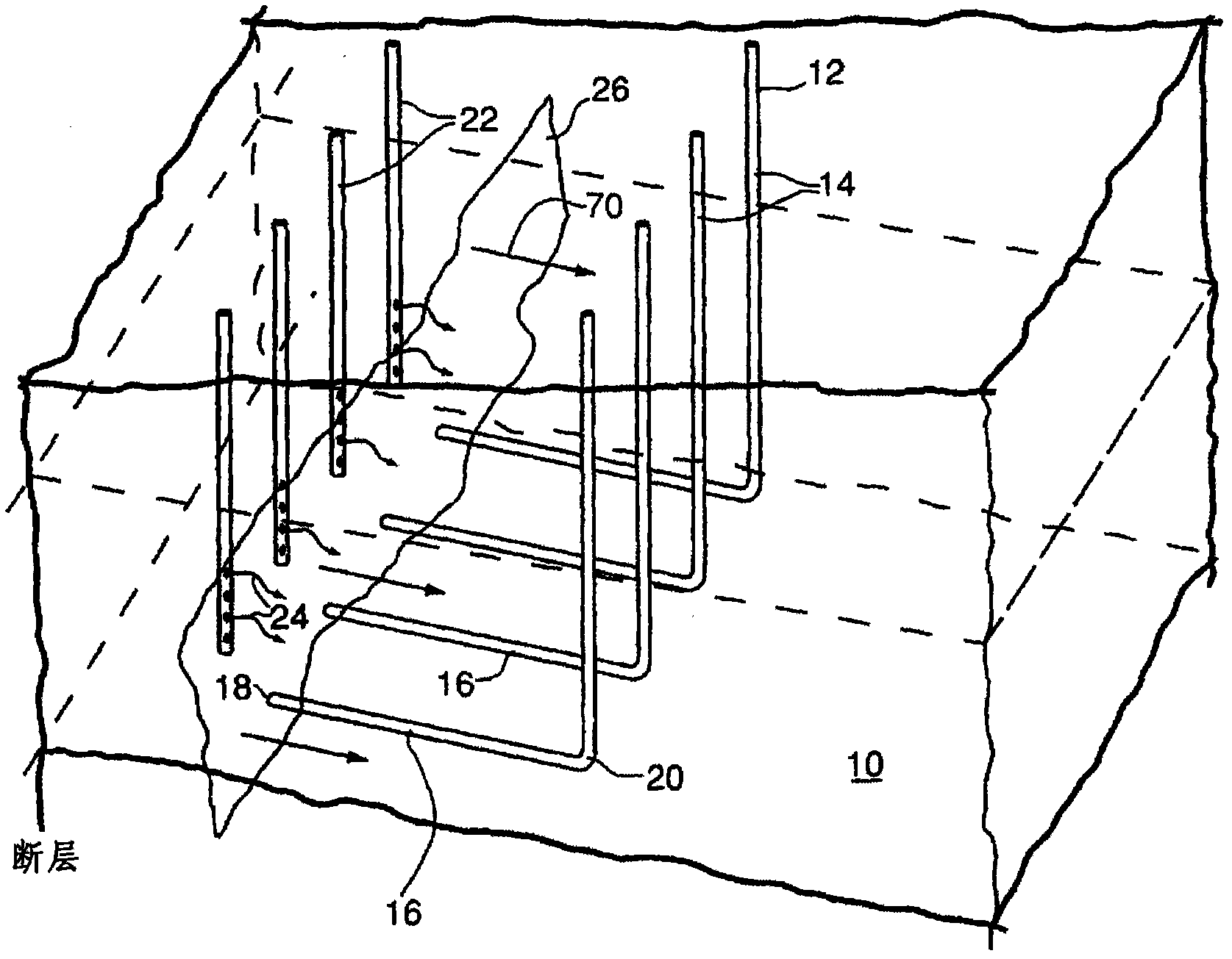
[0056] Figure 1A A translucent schematic diagram showing the layout of wells used in the prior art for in situ recovery of hydrocarbons from an underground hydrocarbon reservoir or formation 10 .

[0057] in particular, Figure 1A Schematically depicts a prior art method for on-site recovery of hydrocarbons disclosed in U.S. Pat. Horizontal leg 16 , substantially horizontal leg 16 has a “toe” portion 18 and a “heel” portion 20 . Horizontal legs 16 of production wells 12 are located in the lower region of hydrocarbon formation 10 and are substantially porous to allow ingress of fluids. A series of injection wells 22 are provided that are located near the "toe" region and extend down into the formation 10 with perforations in the upper region of the oil-bearing reservoir.

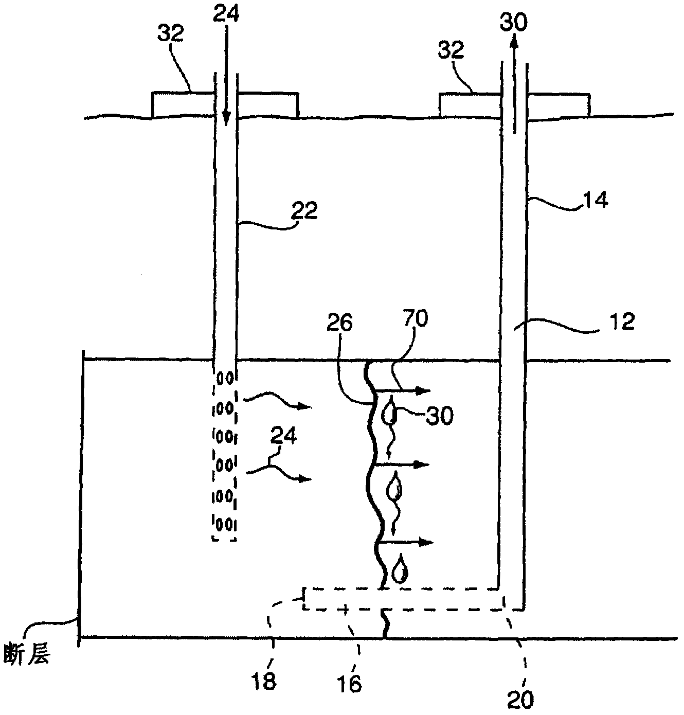
[0058] Figure 1B show Figure 1A A schematic cross-sectional view of an injection well 22 and associated production well 12 is shown.

[0059] exist Figure 1A and Figure 1B In the depicted prior art f...


PUM


Abstract

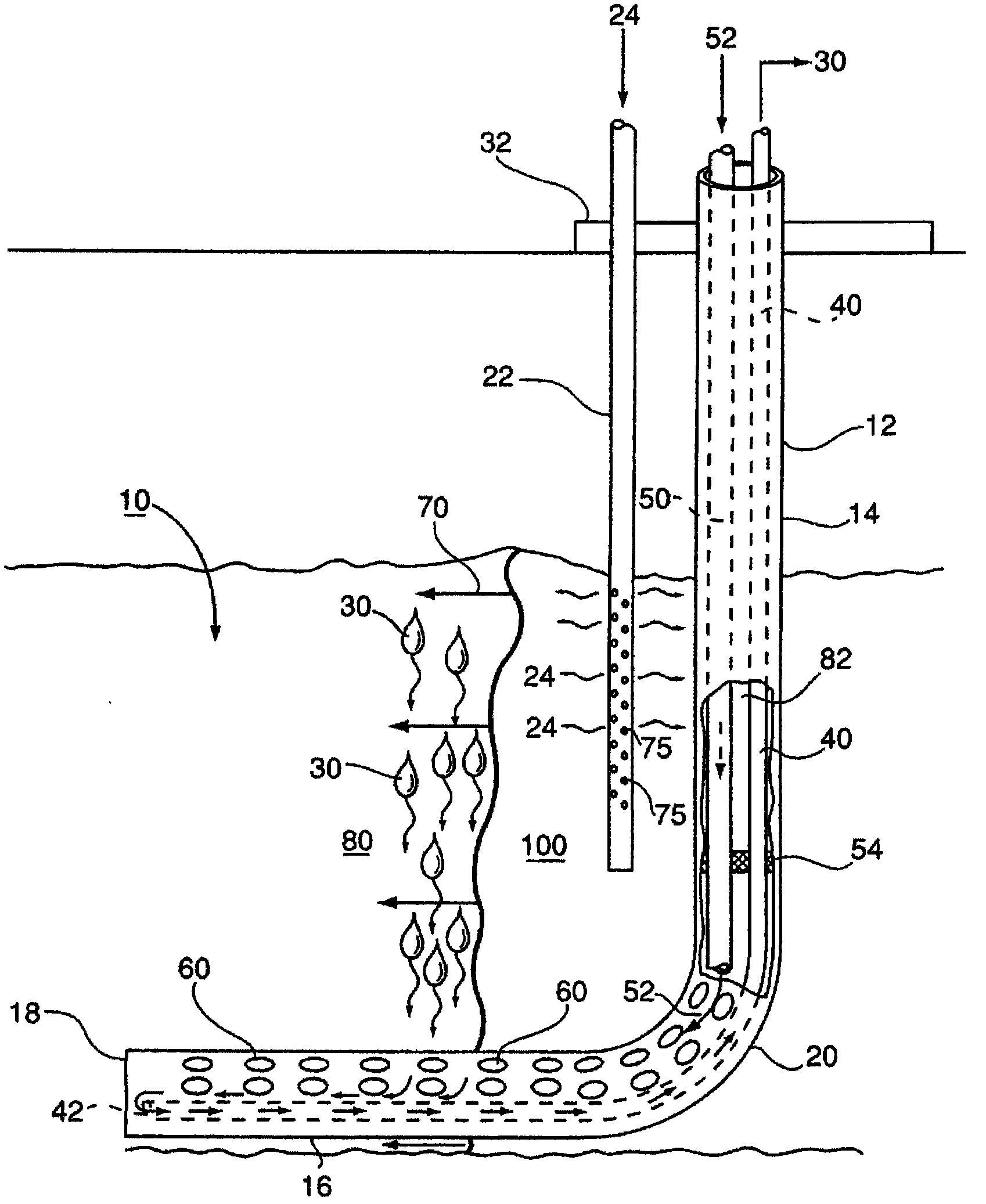
A modified method ofin siturecovery of hydrocarbon from an underground hydrocarbon-containing formation. An "L" shaped production well, having a vertical upper section, and a lower horizontally-extending leg which is positioned low in the hydrocarbon formation, is provided. The horizontal leg connects to the vertical section of the production well at a heel portion and has a toe portion at an opposite end thereof. An oxidizing gas is injected into the formation proximate the vertical section of the production well. A vertical combustion front is created which is caused to sweep outwardly therefrom and laterally within the formation above the horizontal leg, from the heel to the toe of the horizontal leg, causing hydrocarbons in the formation above the horizontal leg to be upgraded and liquify, and thereafter to drain downwardly into the horizontal leg which is permeable, where such liquified hydrocarbons are then delivered to surface via production tubing. A non-oxidizing gas is injected into the heel portion of the horizontal leg via injection tubing contained within the vertical section of the production well. Benefits of the modified method of in situ recovery include decreased costs and lessened environmental impact.

Description

technical field [0001] The present invention relates to an improved method for the recovery of hydrocarbons from subterranean reservoirs by in situ combustion using horizontal production wells. Background technique [0002] U.S. Patent 5,626,191, issued May 6, 1997 (hereinafter the '191 patent), discloses an in situ combustion method for producing hydrocarbons from subterranean hydrocarbon reservoirs utilizing (i) At least one injection well located relatively high in the reservoir for injecting oxidizing gas into the hydrocarbon formation, and (ii) for the production of liquefied or gasified hydrocarbons from the hydrocarbon reservoir well. The production well has a vertical section that communicates with a horizontal leg that extends generally perpendicularly outward from the vertical section and has a "toe" portion and a "heel" portion. The horizontal branch terminates relatively low in the reservoir and communicates with the vertical section at its "heel". Air or othe...

Claims


Application Information

Patent Timeline
Patent Type & Authority Patents(China)
IPC IPC(8): E21B43/243
CPCE21B43/243E21B43/305
Inventor 康芮·爱亚沙吴心洁克里斯·布鲁默
Owner ARCHON TECH LTD
Learn More