Coordinate sensor, electronic device, display device, and light-receiving unit

A technology for a display device and a light-receiving element, which is applied in the directions of identification devices, optics, instruments, etc., can solve the problems of use restrictions, large overall thickness of the device, etc.

Inactive Publication Date: 2011-07-27
SHARP KK
View PDF3 Cites 28 Cited by
  • Summary
  • Abstract
  • Description
  • Claims
  • Application Information

AI Technical Summary

Problems solved by technology

Therefore, the thickness of the plate 230 cannot be formed thinner, so that it is limited in use, and when the above-mentioned coordinate sensor is used in a display device, the thickness of the entire device becomes large.

Method used


Image

  • Coordinate sensor, electronic device, display device, and light-receiving unit
  • Coordinate sensor, electronic device, display device, and light-receiving unit
  • Coordinate sensor, electronic device, display device, and light-receiving unit

Examples


Embodiment approach 1

[0227] According to figure 1 (A) and (b)~ image 3 An embodiment of the present invention will be described.

[0228] In this embodiment, as an example of an electronic device equipped with a coordinate sensor, a liquid crystal display device integrated with a coordinate sensor (integrated with a touch panel) will be described. The above-mentioned liquid crystal display device has a coordinate sensor function (a touch panel function in this embodiment) as a coordinate input function.

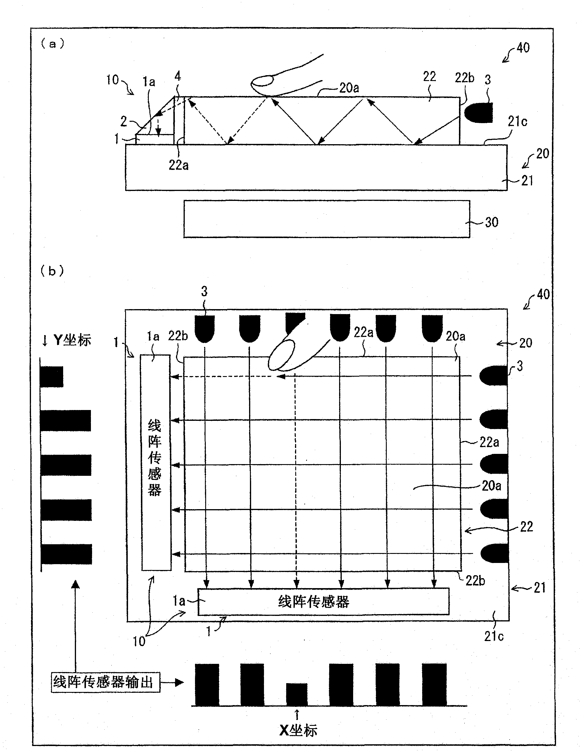
[0229] figure 1 (a) is a cross-sectional view schematically showing a schematic configuration of a main part of the liquid crystal display device of this embodiment, figure 1 (b) is a plan view schematically showing the schematic configuration and coordinate detection principle of the main parts of the liquid crystal display device of this embodiment together with the output of a one dimensional sensor array (hereinafter referred to as a line sensor).

[0230] Such as figure 1 As shown in (a), the ...

Embodiment approach 2

[0285] According to Figure 4 (a) and (b)~ Figure 7 (a) and (b), and Figure 25 Other embodiments of the present invention will be described. In addition, in this embodiment, differences from the above-mentioned Embodiment 1 will be described, and components having the same functions as those of the above-mentioned Embodiment 1 are denoted by the same numbers, and descriptions thereof will be omitted.

[0286] In the first embodiment described above, the case where the infrared LED 3 other than the backlight 30 is used to irradiate the counter substrate 22 with light for detecting the coordinate position has been described as an example. In this embodiment, a case where light for coordinate position detection is irradiated to the counter substrate 22 from the back side of the liquid crystal panel 20 will be described.

[0287] Figure 4 (a) is a cross-sectional view schematically showing a schematic configuration of a main part of the liquid crystal display device of this embodime...

Embodiment approach 3

[0314] According to Figure 8 , And further describe other embodiments of the present invention. In addition, in this embodiment, differences from the above-mentioned Embodiments 1 and 2 will be described, and components having the same functions as those of the above-mentioned Embodiments 1 and 2 are denoted by the same numbers, and descriptions thereof will be omitted.

[0315] In the above-described first and second embodiments, the case where the coordinate sensor 10 (the line sensor 1 and the right-angle prism 2) is provided opposite to the end surface (edge ​​portion) of the counter substrate 22 has been described as an example. In this embodiment, a case where a coordinate sensor is provided to overlap with the counter substrate 22 will be described.

[0316] Figure 8 It is a cross-sectional view schematically showing a schematic configuration of a main part of the liquid crystal display device 40 of this embodiment.

[0317] Such as Figure 8 As shown, the coordinate sensor...


PUM

PropertyMeasurementUnit
refractive indexaaaaaaaaaa

Abstract

The present invention provides a coordinate sensor, an electronic device, a display device and a light-receiving unit. The coordinate sensor (10) is provided with at least two line sensors (1) respectively disposed in the x-axis direction and the y-axis direction, and right angle prisms (2) respectively for changing optical paths of light beams which have passed an image display region of a liquid crystal panel (20). The line sensors (1) are disposed outside the image display region and each comprise a light-receiving surface (1a) parallel to the image display surface of the display panel (20). The right angle prisms (2) guide the light beams in the x-axis direction and the y-axis direction which have passed the image display region to the light-receiving surfaces (1a) of the line sensors(1). The coordinate sensor (10) detects indication coordinates of an object to be detected such as a finger in the image display region by receiving the light beams which have passed the image display region of the liquid crystal panel (20). Consequently, the thin coordinate sensor that enables easy alignment with no reduction in aperture ratio and no restriction on the operation speed is achieved at low cost.

Description

Technical field [0001] The present invention relates to a coordinate sensor, an electronic device and a display device including the coordinate sensor, a coordinate sensor-integrated liquid crystal display device, and a light receiving unit that can be suitably used in the coordinate sensor, wherein the coordinate sensor passes through The light in the image display area of ​​the image display detects the indicated coordinates of the detection target in the image display area. Background technique [0002] Among display devices such as liquid crystal display devices, touch panel-equipped display devices having a touch panel (coordinate sensor) function capable of detecting the touched position when a finger or an input pen touches the panel surface are being developed. [0003] As such a display device with a touch panel, a display device using a touch panel such as a so-called resistive film method or an electrostatic capacitance type has been mainly used. However, in such a disp...

Claims


Application Information

Patent Timeline
Patent Type & Authority Applications(China)
IPC IPC(8): G06F3/041G02F1/1333G02F1/13357G02F1/1343G06F3/042G09F9/00
CPCG06F2203/04109G06F3/0428G06F3/0421G02F1/13338
Inventor 浜田浩宫崎伸一野间干弘高滨健吾和田正一方志教和小田巧一水野之雄
Owner SHARP KK
Why Eureka
Try Eureka