Rolling robot

A robot and rolling bearing technology, applied in the field of rolling robots, can solve problems such as inability to turn and realize complex gait, and achieve the effect of high rigidity, less degrees of freedom, and simple control

Active Publication Date: 2011-08-10
BEIJING JIAOTONG UNIV
View PDF3 Cites 14 Cited by
  • Summary
  • Abstract
  • Description
  • Claims
  • Application Information

AI Technical Summary

Problems solved by technology

However, it is limited to only one degree of freedom in the four-bar mechanism, so it can

Method used


Image

  • Rolling robot
  • Rolling robot
  • Rolling robot

Examples


Example Embodiment

[0038] The present invention will be further described in conjunction with accompanying drawings.

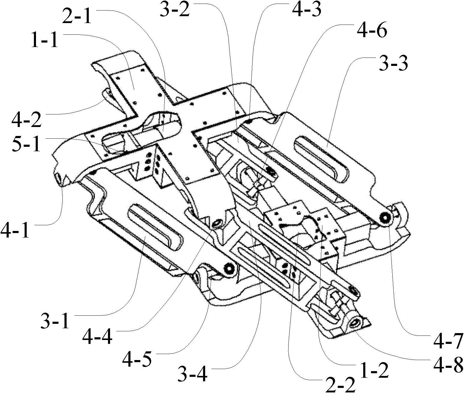
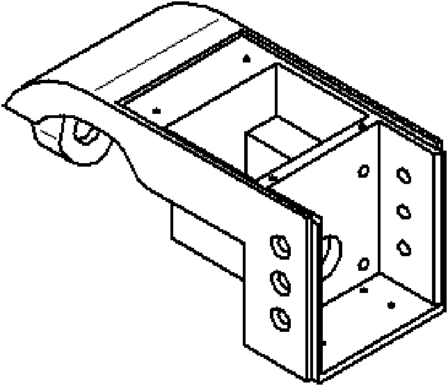
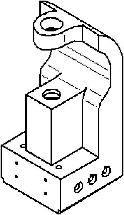
[0039] A rolling robot such as figure 1 As shown, the robot includes: first and second cross-shaped members 1-1, 1-2; first to fourth connecting rods 3-1, 3-2, 3-3, 3-4; first to fourth Eight cross shafts 4-1, 4-2, 4-3, 4-4, 4-5, 4-6, 4-7, 4-8; first and second drive motors 2-1, 2-2; First and second shaft couplings 5-1, 5-2; the connection between the described parts is:

[0040] The s end of the first cross shaft 4-1 is inserted into the seventeenth rolling bearing 8-17 of the first cross member 1-1, and the t end of the first cross shaft 4-1 is inserted into the second end of the first connecting rod 3-1. In the rolling bearing 8-2, the u end of the first cross shaft 4-1 is inserted into the first rolling bearing 8-1 of the first connecting rod 3-1, and the v end of the first cross shaft 4-1 is inserted into the first cross member 1 -1 Eighteenth rolling bearing 8-18, such...


PUM


Abstract

The invention discloses a rolling robot which comprises first and second cross-shaped components (1-1, 1-2), first to fourth connecting rods (3-1, 3-2, 3-3, 3-4), first to eighth joint crosses (4-1, 4-2, 4-3, 4-4, 4-5, 4-6, 4-7, 4-8) and first and second driving motors (2-1, 2-2). The first and second cross-shaped components (1-1, 1-2) are connected with the first to fourth connecting rods (3-1, 3-2, 3-3, 3-4) through the first to eighth joint crosses (4-1, 4-2, 4-3, 4-4, 4-5, 4-6, 4-7, 4-8). The first and second driving motors (2-1, 2-2) are respectively arranged on the first and second cross-shaped components (1-1, 1-2). The formed rolling robot can realize rolling in the random direction in the plane by utilizing inertia and can be used for application such as planetary exploration, military reconnaissance and the like.

Description

technical field [0001] The invention relates to a rolling robot, which is used for planet detection, military reconnaissance, disaster rescue and the like. Background technique [0002] Mobile robots mainly use wheeled mobile mechanisms in a structured ground environment. In recent years, with the increase in the use of planetary exploration, military reconnaissance, and disaster rescue, the innovation of new mobile mechanisms has become more and more urgent, and there are also emerging Many excellent and practical inventions have been produced. [0003] Chinese patent announcement number CN2789106Y discloses a "single power rolling four-bar mechanism", which removes the fixed constraints between the frame rod and the ground of the traditional four-bar mechanism, and uses a motor to drive the movement of the non-frame. The sudden stop of the mechanism converts the local kinetic energy of the mechanism into the kinetic energy of the whole mechanism including the frame, so th...

Claims


Application Information

Patent Timeline
IPC IPC(8): B62D57/02
Inventor 姚燕安李锐明
Owner BEIJING JIAOTONG UNIV
Why Eureka
Try Eureka