Three-finger three-degree-of-freedom configuration robot gripper

A robot hand, degree of freedom technology, applied in the field of robots, can solve the problems of low reliability, many degrees of freedom, difficult to grasp, etc., to achieve the effect of improving operation ability, reducing degrees of freedom, and strong operation ability

Active Publication Date: 2016-03-02
哈工大机器人创新中心有限公司
View PDF7 Cites 15 Cited by
  • Summary
  • Abstract
  • Description
  • Claims
  • Application Information

AI Technical Summary

Problems solved by technology

One type is a robotic dexterous hand that aims to imitate the ability of a human hand. It has strong grasping ability and operating ability, but its main problems are many degrees of freedom, complex structure, low reliability, and complex control algorithms, which limi

Method used


Image

  • Three-finger three-degree-of-freedom configuration robot gripper
  • Three-finger three-degree-of-freedom configuration robot gripper
  • Three-finger three-degree-of-freedom configuration robot gripper

Examples


specific Embodiment approach 1

[0036] Specific implementation mode one: as Figure 1 to Figure 20Shown, a kind of robot gripper of three-finger three-degree-of-freedom configuration, comprises palm 7, connecting flange 8, circuit board 14, rotating supporting part one, rotating supporting part two and three fingers (referring to three fingers), so The three fingers described above have the same structure, and the three fingers are respectively finger one 10, finger two 11 and finger three 12; the palm 7 includes a palm cover 51, a palm shell 52, a support 13 and a support two 39, and The upper end of the palm shell 52 is fixedly connected with the palm cover plate 51 (by screws), the lower end of the palm shell 52 is fixedly connected with the connecting flange 8 (by screws), and the first bracket 13 and the second bracket 39 are all arranged on the palm shell 52. Inside and fixedly connected with the palm cover plate 51 (by screws), the circuit board 14 is arranged in the palm shell 52 and fixedly connecte...

specific Embodiment approach 2

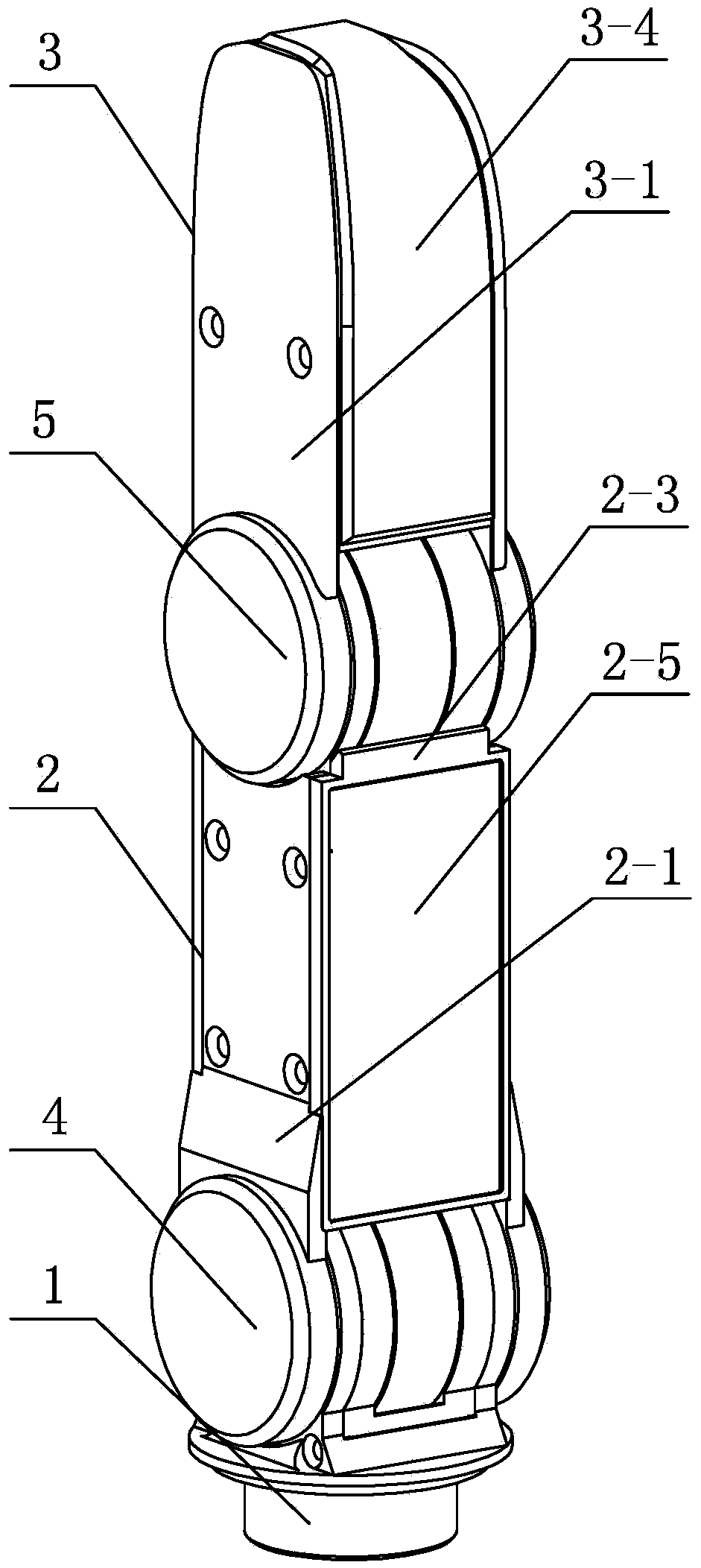
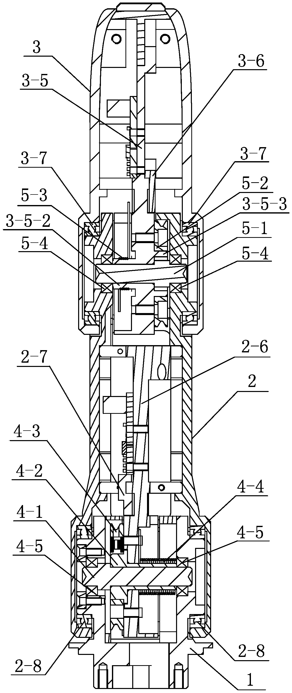
[0039] Specific implementation mode two: as Figure 1 to Figure 12 , Figure 19 ~ Figure 22 As shown in the first embodiment, a three-finger three-degree-of-freedom robot gripper described in the first embodiment, the first rotating support part includes a supporting bearing 53 and an end cover 54, and the second rotating supporting part includes a support Bearing two 55 and end cap two 56, each of the fingers includes base 1, proximal knuckle 2, terminal knuckle 3, tendon sheath driving mechanism one, connecting end cap 57 and two pitching and rotating joints, the said The two pitching and rotating joints are the base joint 4 and the terminal joint 5 respectively; the proximal knuckle 2 includes the proximal knuckle shell, the proximal knuckle force transmission member 2-6 and two proximal knuckle support bearings 2-8, so The said proximal knuckle shell comprises the proximal knuckle left panel 2-1, the proximal knuckle right panel 2-2, the proximal knuckle front cover 2-3 a...

specific Embodiment approach 3

[0042] Specific implementation mode three: as Figure 13 to Figure 16 , Figure 23 As shown, a robot gripper with three fingers and three degrees of freedom described in Embodiment 2, the three-finger base joint synchronous bending mechanism includes a base joint synchronous rotation driver 9, a base joint bushing 2 16, a base joint Joint worm 17, base joint worm gear 18, base joint tendon wheel 2 19, base joint shaft 2 20, base joint end cover 22, non-contact position sensor 1, two base joint support bearings 15, two base joint support bearings Two 21 and three base joint sheath tubes 33; the output shaft of the base joint synchronous rotation driver 9 is fitted with a base joint sleeve 2 16, and the middle part of the base joint worm 17 is provided with a through cavity along the axial direction, The base joint shaft sleeve 2 16 is fixedly inserted into the through cavity of the base joint worm 17, and the two ends of the base joint worm 17 are respectively supported and fi...


PUM


Abstract

The invention discloses a three-finger three-degree-of-freedom configuration robot gripper, and belongs to the technical field of robots. The robot gripper is a robot gripper between a dexterous gripper and a single-degree-of-freedom holder, and can grip objects in different shapes and sizes. The bottom of a first finger is fixed to the upper surface of a palm cover plate; the bottom of a second finger is arranged in a housing and is rotationally connected with the palm cover plate; the bottom of a third finger is arranged in the housing and is rotationally connected with the palm cover plate; three finger base joint synchronous bending mechanisms, three finger tail end joint synchronous bending mechanisms, the second finger and the third finger are coupled to an opposite-direction rotating mechanism relative to a palm and are arranged in the housing; the three finger base joint synchronous bending mechanisms drive base joints of the three fingers to synchronously bend and rotate through base joint tendon sheath driving mechanisms of the three fingers; and the three finger tail end joint synchronous bending mechanisms drive tail end joints of the three fingers to synchronously bend and rotate through tail end joint tendon sheath driving mechanisms of the three fingers. The three-finger three-degree-of-freedom configuration robot gripper is used to grip the objects.

Description

technical field [0001] The invention relates to a robot gripper, which belongs to the technical field of robots. Background technique [0002] As the operating tool at the end of the robot, the robot gripper has an important impact on the working level of the robot system, such as its gripping ability, operating ability, and reliability. [0003] There are two main types of robotic grippers currently in use. One type is a robotic dexterous hand that aims to imitate the ability of a human hand. It has strong grasping ability and operating ability, but its main problems are many degrees of freedom, complex structure, low reliability, and complex control algorithms, which limit its wide application. . The other type is a gripper with only a single degree of freedom, which is simple in action and high in reliability. The problem is that it is difficult to grasp objects of different shapes and sizes, and its versatility and scalability are poor. To sum up, in the field of robo...

Claims


Application Information

Patent Timeline
IPC IPC(8): B25J15/00B25J15/10B25J9/16
CPCB25J9/163B25J15/0009B25J15/103
Inventor 刘伊威金明河
Owner 哈工大机器人创新中心有限公司
Why Eureka
Try Eureka