Air valve seating control device for hydraulic drive air valve mechanism of engine

A valve mechanism and control device technology, applied in engine components, machines/engines, valve devices, etc., can solve the problems of valve U-turn, high valve seating speed, valve seat impact, etc., and achieve the effect of stable seating and reasonable flow area

Inactive Publication Date: 2011-08-10
SHANDONG UNIV
View PDF5 Cites 5 Cited by
  • Summary
  • Abstract
  • Description
  • Claims
  • Application Information

AI Technical Summary

Problems solved by technology

For the hydraulically driven valve mechanism, due to the cancellation of the direct control of the valve by the camshaft, the valve seat speed is too high, which has a serious impact on the valve seat, and even causes a serious accident of the valve turning around.

Method used


Image

  • Air valve seating control device for hydraulic drive air valve mechanism of engine
  • Air valve seating control device for hydraulic drive air valve mechanism of engine
  • Air valve seating control device for hydraulic drive air valve mechanism of engine

Examples


specific Embodiment 2

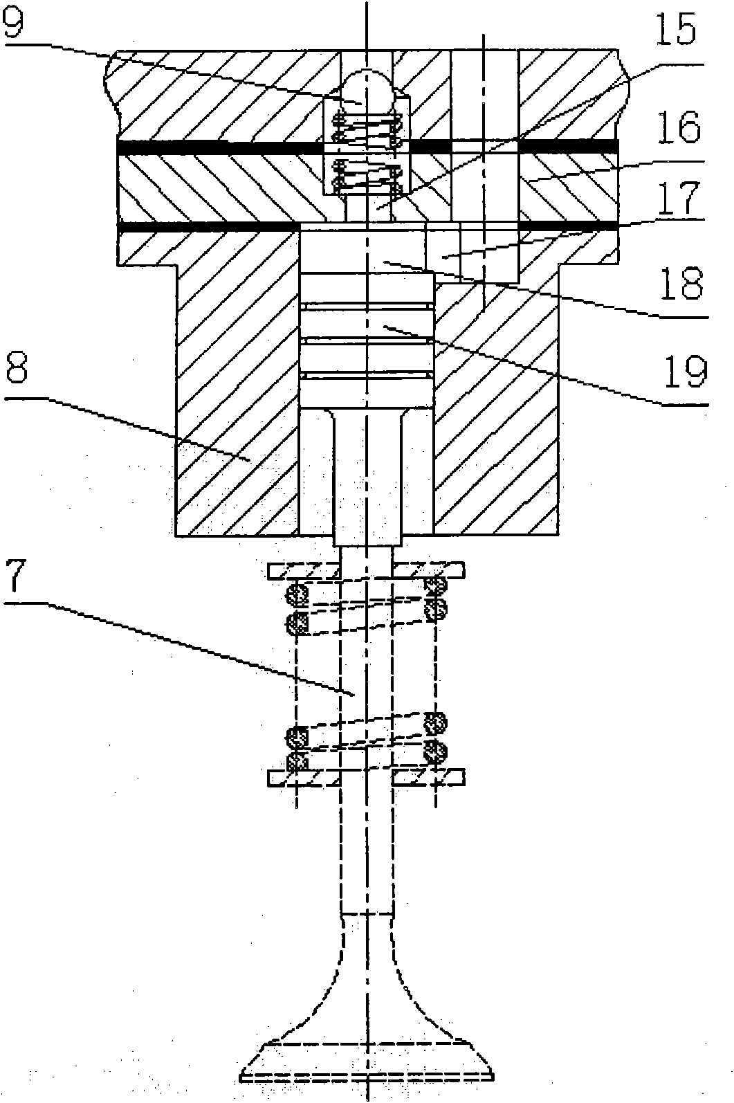
[0017] Such as image 3 As shown, the check valve 9 is installed in the bypass oil passage 15; the variable throttle passage is composed of the outer circular side of the flat top piston 19 and the side oil passage hole 17 on the piston sleeve 8, and controls the minimum flow area of ​​the main oil passage ; The piston cavity 18 is formed by the piston 19, the piston sleeve 8 and the piston sleeve cover 16. The piston cavity 18 is connected with the hydraulic system through the bypass oil passage 15 and the main oil passage provided with the side oil passage hole 17 . Its specific working process is as follows:

[0018] The first stage is the valve opening process. In this process, the working process of the device can be divided into two periods. In the first period, because the piston 19 covers most of the area of ​​the side oil passage hole 17 to form a variable throttling passage, the flow area of ​​the variable throttling passage is small at this time, and the throttli...


PUM


Abstract

The invention relates to an air valve seating control device for a hydraulic drive air valve mechanism of an engine, which mainly comprises a hydraulic piston, a hydraulic oil channel, a one-way valve, a hydraulic piston cavity, a variable throttling channel and the like. The hydraulic piston cavity is provided with a main oil channel of the variable throttling channel and a bypass oil channel with the one-way valve and is communicated with a hydraulic system; and the hydraulic piston is used for driving an air valve to move. The air valve seating control device adopts the one-way valve to lead the hydraulic drive air valve mechanism to have different hydraulic circulation areas in the opening and closing process of the air valve; with the adoption of the variable throttling channel, the throttling circulation areas can be changed along with the air valve lift in the closing process of the air valve, and the air valve seating speed of the hydraulic drive air valve mechanism of the engine is furthermore controlled to realize the soft landing of the air valve.

Description

technical field [0001] The invention relates to a gas distribution mechanism of a four-stroke engine. Especially the hydraulic variable valve mechanism that drives the valve movement by hydraulic drive. technical background [0002] The fully variable valve mechanism can realize the continuous variable of the maximum lift of the valve, the continuous opening angle of the valve and the timing of the valve distribution, so it has a good effect of energy saving and emission reduction. In the traditional valve train, the valve is driven by a cam, and the seating speed of the valve can be directly controlled by the cam profile. The current fully variable valve train usually adopts hydraulic drive mode, such as cam hydraulic drive mode, electro-hydraulic drive mode and so on. For the hydraulically driven valve mechanism, since the direct control of the valve by the camshaft is cancelled, the valve seat speed is too high, which has a serious impact on the valve seat, and even cau...

Claims


Application Information

Patent Timeline
Patent Type & Authority Applications(China)
IPC IPC(8): F01L9/02F01L9/10
Inventor 谢宗法顾珂韬
Owner SHANDONG UNIV
Why Eureka
Try Eureka