

Movable air conditioner
A technology for mobile air conditioning and installation space, applied in the direction of air conditioning system, heating method, space heating and ventilation, etc., to prevent the outflow of indoor air, prevent the inflow of outdoor air, easy installation and removal
- Summary
- Abstract
- Description
- Claims
- Application Information
AI Technical Summary
Problems solved by technology
Method used
Image

Examples
Embodiment Construction
[0040] Hereinafter, embodiments of the present invention will be described with reference to the accompanying drawings.
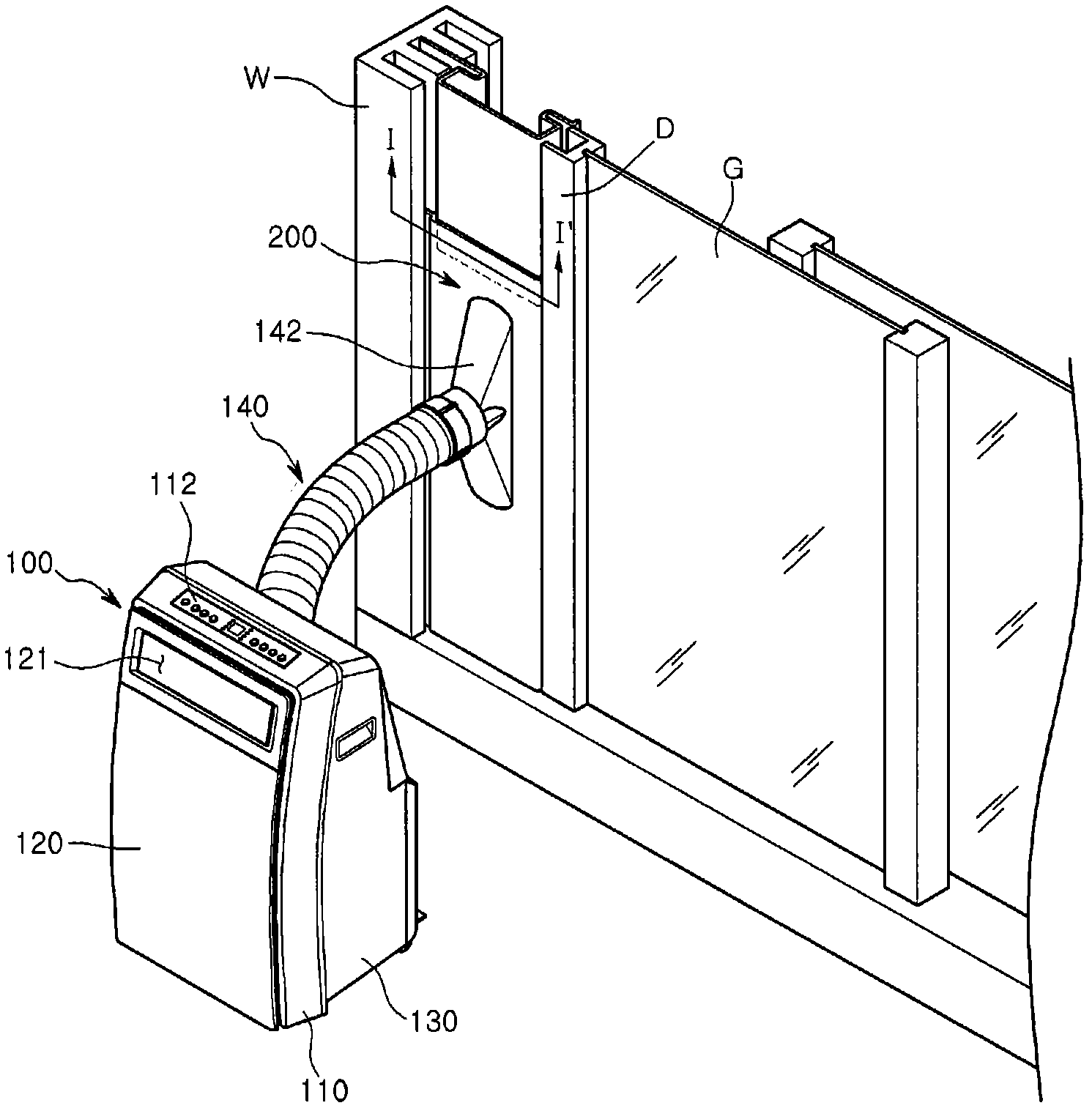
[0041] figure 1 It is a perspective view of the appearance of the installation shape of the portable air conditioner according to the embodiment of the present invention.
[0042] refer to figure 1 , by accommodating the components in the mobile air conditioner 100 according to the embodiment of the present invention in the front frame 110 and the front panel 120 constituting the front appearance and the rear frame 130 constituting the rear appearance to protect the components.
[0043] Although not shown in the drawing, a compressor, a condenser, an expansion member including an expansion valve and a capillary tube, and an evaporator are housed inside the air conditioner 100 , wherein the evaporator and the condenser may be disposed on upper and lower sides, respectively. A condenser fan for forcibly sucking indoor air into the condenser, and an evaporat...
PUM
 Abstract
Description
Claims
Application Information