Lighting device

A technology for lighting equipment and equipment, which is applied to lighting and heating equipment, lighting devices, components of lighting devices, etc., can solve the problems of decreased heat dissipation, reduced lamp head area, unable to obtain heat dissipation, etc., and achieves easy loading and unloading. Effect

Active Publication Date: 2011-08-10
TOSHIBA LIGHTING & TECH CORP
View PDF1 Cites 9 Cited by
  • Summary
  • Abstract
  • Description
  • Claims
  • Application Information

AI Technical Summary

Problems solved by technology

[0005] However, in the state where the cap of the lamp device is mounted on the socket device, the area of ​​the cap exposed to the outside becomes smaller in the mounting structure, so the heat dissipation performance is reduced.
In addition, it is also conceivable to conduct heat from the cap to the socket device side, but since there is a gap between the cap and the socket device and they are not in close contact with each other, there is a possibility that the heat of the cap cannot be efficiently transferred. The problem that sufficient heat dissipation cannot be obtained to the lamp holder device side

Method used


Image

  • Lighting device
  • Lighting device
  • Lighting device

Examples


Embodiment Construction

[0076] Hereinafter, one embodiment of the present invention will be described with reference to the drawings.

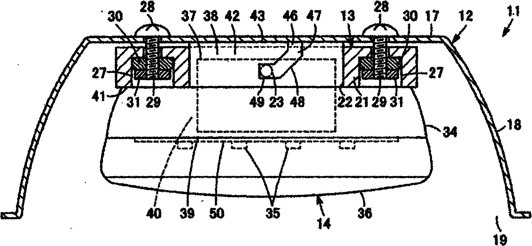
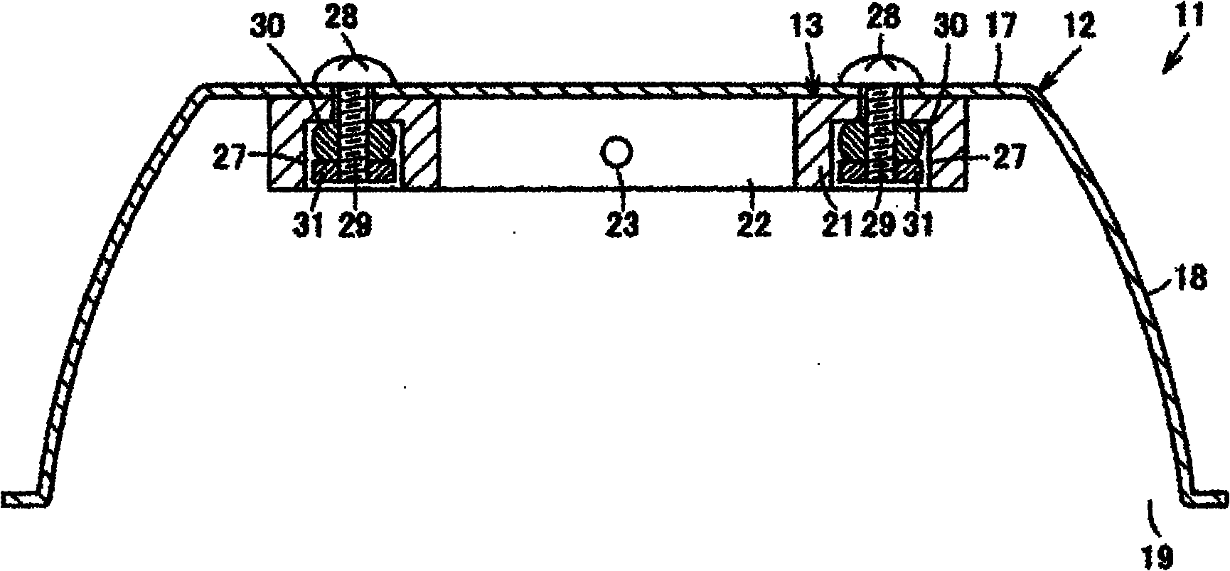
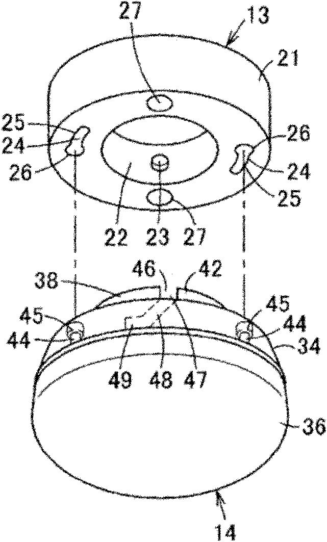
[0077] Figure 1 to Figure 4 Showing the first embodiment, figure 1 It is a cross-sectional view of lighting equipment constructed by assembling a lamp device on a lamp socket device, figure 2 is a sectional view of the lighting equipment with the lamp unit removed, image 3 is a perspective view of an exploded state of a lamp base unit and a lamp unit, Figure 4 It is a perspective view of a light device.

[0078] The lighting equipment 11 is, for example, a downlight. Detachable flat lamp unit 14 . In addition, hereinafter, regarding the directional relationship of the above-mentioned components such as the up-down direction, the flat lamp device 14 is installed horizontally as a reference, with one side of the lamp device 14, that is, the base side, as the upper surface side, and the other side of the lamp device 14 as the reference. One side, that is, the...


PUM


Abstract

A lighting device (11) capable of efficiently dissipating heat of a lamp device (14) mounted to a socket device (13). When the lamp device (14) is mounted to the socket device (13), a fitting section (38) of the lamp device (14) makes contact with a device body (12) and, at the same time, an elastic body (30) presses the fitting section (38) to the device body (12) in such a manner that the fitting section (38) is in close contact with the device body (12). Heat created by lighting of an LED (35) of the lamp device (14) is transferred from the fitting section (38) to the device body (12). Thus, the heat of the lamp device (14) is efficiently dissipated.

Description

technical field [0001] The present invention relates to lighting equipment using a lamp device having a flat shape, a lamp head provided on one side and a light source arranged on the other side. Background technique [0002] Conventionally, there is a lamp device using a GX53-type cap under the IEC (International Electrical Standards Conference) standard. This lamp device has a flat lamp device main body, a GX53 type base is provided on the upper surface side of the lamp device main body, and a planar light source using a fluorescent lamp or an LED or the like is arranged on the lower surface side of the lamp device main body. , a lighting circuit for lighting the light source is accommodated inside the lamp device main body. Protruding from the lamp head is a pair of lamp pins having a large diameter portion at the end. In addition, the lamp pins of the lamp device are inserted into the socket device, and the lamp pins are hooked to the socket device by rotating the lamp...

Claims


Application Information

Patent Timeline
Patent Type & Authority Applications(China)
IPC IPC(8): F21S2/00F21V19/00F21V29/00F21Y101/02
CPCF21Y2101/02F21V29/20F21V19/006F21K9/30H01R33/9456F21K9/00F21V19/001F21V29/267F21V29/2206F21V29/004F21V29/67F21V29/73F21V29/74F21K9/20F21Y2115/10Y10T29/49879F21V17/00F21V19/00F21V29/00
Inventor 渡边智清水圭一长田武清水惠一田中敏也大泽滋久安武志大武宽和河野仁志酒井诚
Owner TOSHIBA LIGHTING & TECH CORP
Why Eureka
Try Eureka