Solid state low bay light with integrated and sealed thermal management

a technology of thermal management and led lighting, applied in lighting and heating equipment, semiconductor devices for light sources, lighting applications, etc., can solve the problems of requiring more precise current management systems, limited light output range, and relatively expensive leds powerful enough for room lighting, etc., to achieve efficient heat dissipation and improve air flow

Inactive Publication Date: 2014-04-08
INFINILUX
View PDF3 Cites 45 Cited by
  • Summary
  • Abstract
  • Description
  • Claims
  • Application Information

AI Technical Summary

Benefits of technology

[0023]In view of the foregoing background, it is therefore an object of the invention to provide a lighting fixture utilizing LED light sources for illumination of commercial, outdoor and other large area applications that incorporates efficient heat dissipation and improved air flow.
[0025]In another aspect of the current invention, a lighting fixture body is configured with a heat sink having a chimney tube with internally facing finned heat sink arrangement for providing enhanced convective air flow through the light fixture body. The chimney tube is generally configured in a vertical direction to allow heated air to naturally rise as it is heated and expands into a body canister. The heat sink and fin configuration improves convective air flow patterns for efficiently moving heat away from an LED heat source and providing efficient thermal conductive pathways and convective air flow pathways that generate improved heat dissipation through the housing and into the environment, thus reducing internal heat storage. The resulting high thermal flow rates and convection cooling system is capable of efficiently dissipating the waste heat from an LED lighting module without the need for active cooling, such as a fan or refrigeration. In contrast to conventional naturally-cooled heat sink designs, relying solely on considerations of form factor, surface area, and mass to dissipate generated thermal loads, in its various aspects and particular implementations, embodiments of the present invention additionally contemplate creating and maintaining a “chimney effect” within the fixture to eliminate heat.
[0026]In yet another aspect of the invention, a heat sink is configured with tapered fins for allowing enhanced convective thermal currents. The heat sink fins are internally directed from the heat sink tube and are tapered, being wider at one end of the tube and narrower at the other. The fin shape provides for a higher thermal energy transfer where the fins are wider and lower thermal energy transfer where the fins are narrower. This heat differential cause air to flow from areas of low heat to areas of high heat, generating convective currents as a result. These convective currents enhance air flow and thus dissipation of heat from the heat sink more quickly compared to other heat sink designs.

Problems solved by technology

An LED is often small in area and has limited light output range.
LEDs powerful enough for room lighting are relatively expensive and require more precise current and heat management systems than compact florescent lamp sources of comparable output.
One limitation in the use of LED lighting is excessive heat generation and adequate thermal management.
At higher currents, such designs further increase the heating of the LED, creating more concern regarding light output.
Over-driving an LED in high ambient temperatures may result in overheating the LED package, eventually leading to device failure.
Most heat sink designs simply do not have the aesthetic appeal required for mass adoption in real world lighting applications, or do not adequately remove heat sufficient to maintain luminescent integrity and LED life.
However, there is an impediment or restrictor in the thermal transfer path from the light emitting diodes to the heat sink; namely, a resin filler or adhesive is used to attach the LED array to the heat sink, which is a very poor heat conductor.
These type of venting arrangement are not particularly effective in hot climates, and simply trap hot air within the enclosure with little heat exchange with the environment.
Since the lens, reflector, and lamp assembly is not designed to enhance air flow excess heating in the signal housing may degrade the optical performance of the unit.
This heat sink arrangement is complex from a manufacturing perspective and increases cost.
The design is also limited in that if the ambient are is close to the same temperature as the heat sink no additional cooling can occur.
This is problematic in hot climates.
This design and related manufacturing process is complicated.
Further, any diminished integrity of the heat tube will allow fluid to discharge from the tube and the system will fail.
One problem with this design is that the air circulates in an enclosed system and thus cannot dissipate hot air from the system.
Although the fan produces increased air flow, it also undesirably and materially increases design, manufacturing and complexity of the lamp.
It also generates audible sound from the fan, which is undesirable many applications.
This fanning is useful for enhancing air circulation, but increases the number of moving parts which create maintenance issues.
Failure to detect a failing fan can cause the LED to overhead and shorten its life.
This design depends on removal of heat to the surrounding environment and the aesthetics are not particularly desirable for most applications.
Although this is an improvement over previous designs there are limitation in that air circulation within most LED fixture designs is contained in an enclosure, limiting air flow and requiring venting.
Mueller's design is complex, requiring significant increases in cost as a result of increased component content and manufacturing complexity.
Although effective, the costs for such a system in many applications if prohibitive and less costly solutions are desirable.

Method used


Image

  • Solid state low bay light with integrated and sealed thermal management
  • Solid state low bay light with integrated and sealed thermal management
  • Solid state low bay light with integrated and sealed thermal management

Examples


Embodiment Construction

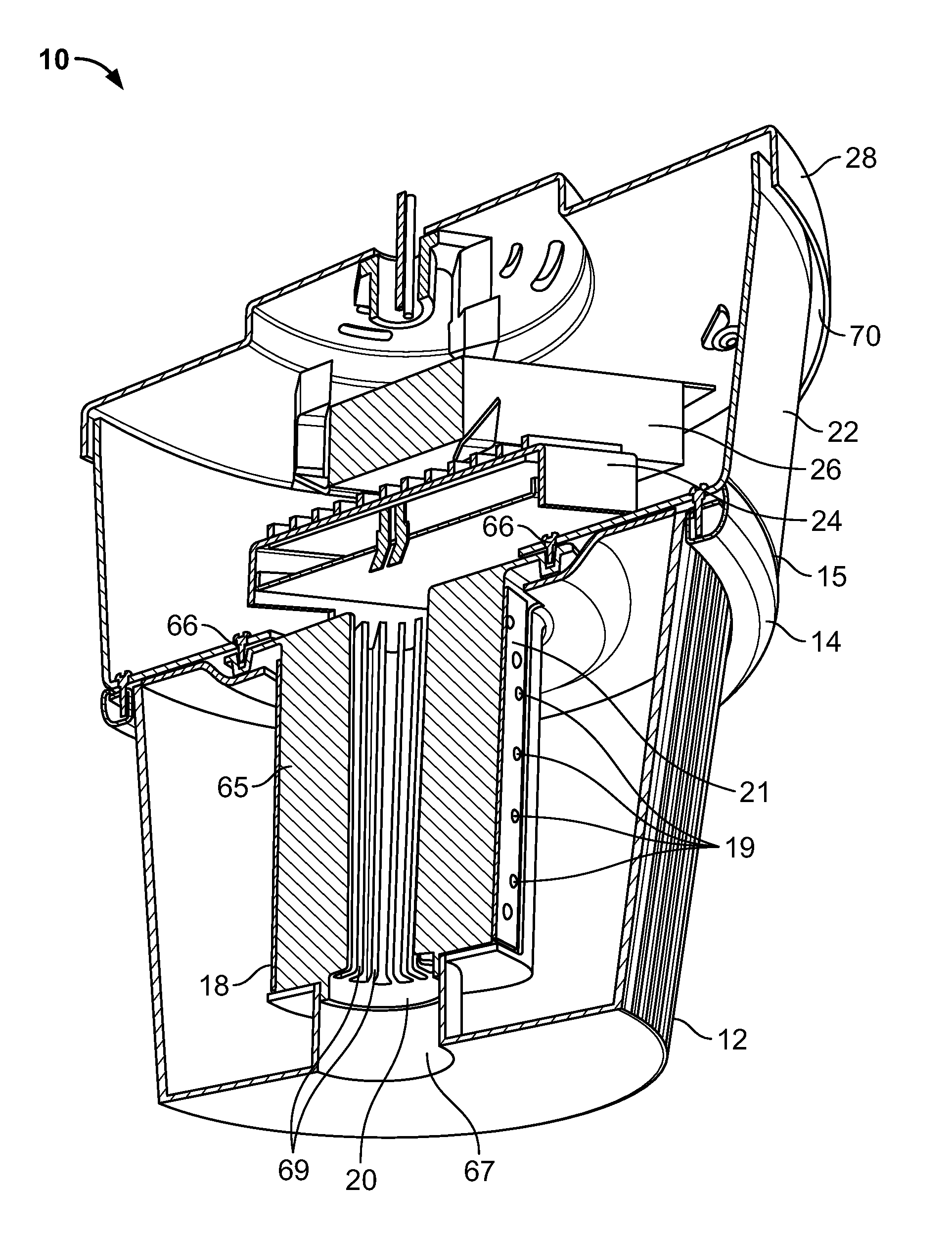
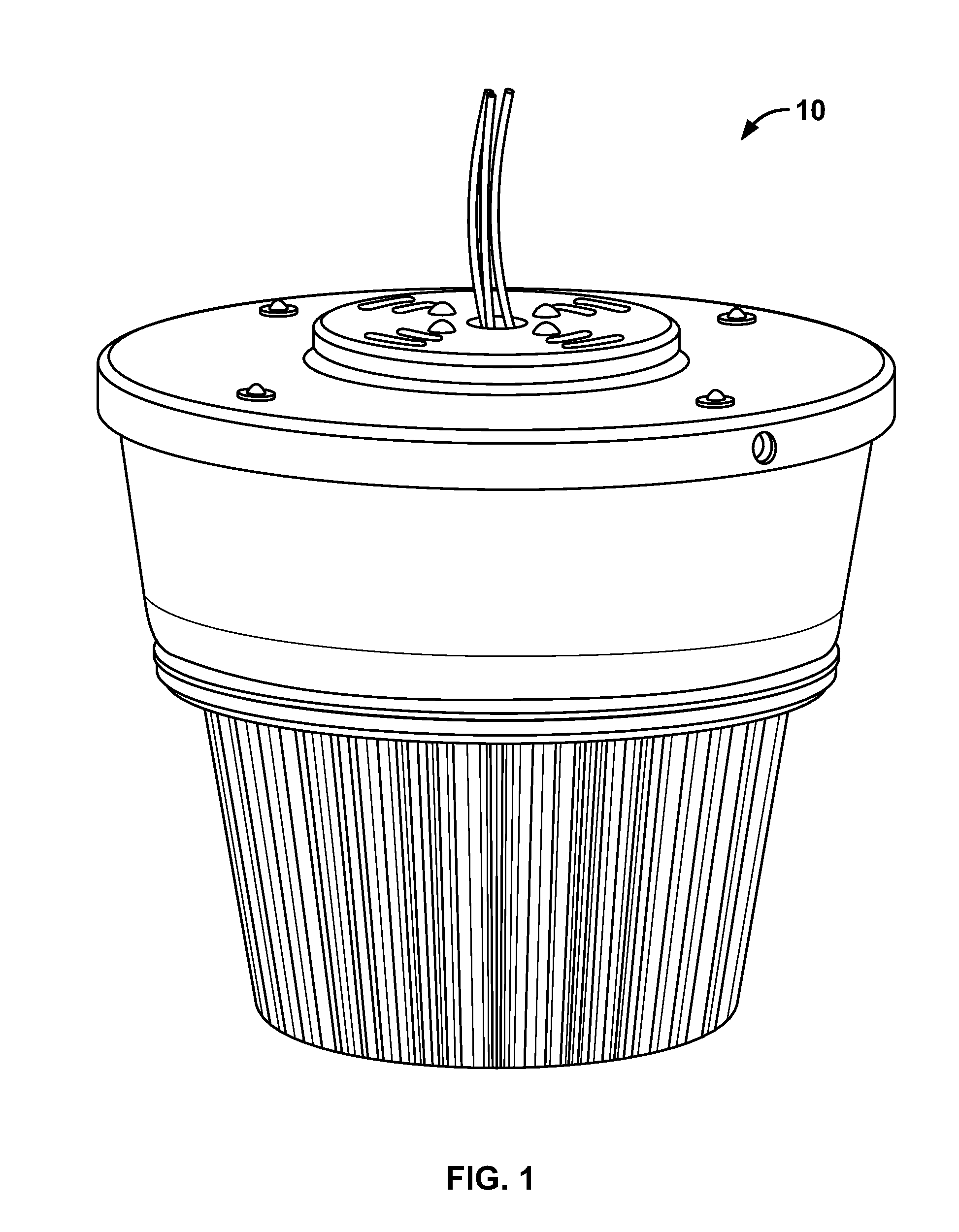
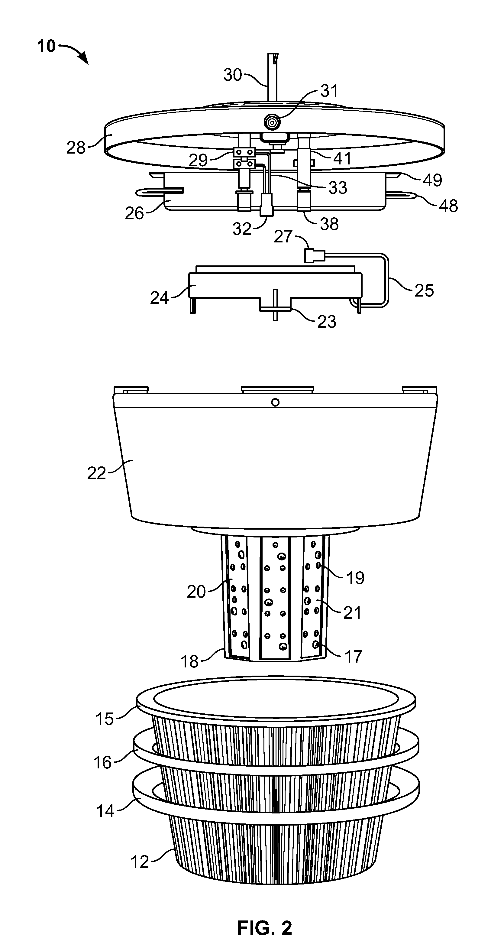
[0052]The present invention provide for a Solid State Low Bay Light with integrated and sealed thermal management

[0053]The present invention will now be described more fully hereinafter with reference to the accompanying drawings in which preferred embodiments of the invention are shown. This invention may, however, be embodied in many different forms and should not be construed as limited to the illustrated embodiments disclosed. Rather, these embodiments are provided so that this disclosure will be thorough and complete, and will fully convey the scope of the invention to those skilled in the art. Like numbers refer to like elements throughout. The access system will now be described in detail, with reference made to FIGS. 1-14.

[0054]The foregoing description illustrates exemplary implementations, and novel features, of aspects of a solid state low bay light with integrated and sealed thermal management. Alternative implementations are suggested, but it is impractical to list all ...


PUM


Abstract

A lighting fixture utilizing LED light sources for illumination of commercial, outdoor and other large area applications incorporates efficient heat dissipation and improved convective air flow. An integrated heat transfer assembly is disclosed that is configured to enhance heat dissipation by providing an efficient thermal conductive pathway for radiation of heat to an external environment. The lighting fixture body is configured with a lens body and heat sink having a chimney tube with internally facing finned heat sink arrangement for providing enhanced convective air flow through the light fixture body. When the heat sink transfers heat from the LED light sources during operation so as to create heated air surrounding the heat sink, ambient air is drawn through the chimney and the heated air is exhausted through air gaps so as to create a conductive air current with the environment. The heat sink fins are configured to enhance the natural air draw through the chimney by tapering the surface areas of the fins.

Description

RELATION TO OTHER PATENTS[0001]This application claims benefit, under 35 U.S.C. 119(e), of U.S. Provisional Application Ser. No. 61 / 314,507, filed Mar. 16, 2010, entitled “Solid State Low Bay Light with Integrated and Sealed Thermal Management”, which is fully incorporated herein by reference.BACKGROUND[0002]1. Field of Invention[0003]The present disclosure generally relates to solid state low bay LED lighting apparatus and systems with integrated thermal management.[0004]2. Related Art[0005]Practical applications for Light Emitting Diode (LED) technology have evolved rapidly in the recent past. An LED is a semiconductor based light source. LEDs have been used as indicator lamps in many devices, and are increasingly used for residential, commercial, industrial and street illumination applications. LED illumination devices are used in applications as diverse as consumer electronic products such as remote controllers, televisions, DVD players, and other domestic appliances. They are a...

Claims


Application Information

Patent Timeline
Patent Type & Authority Patents(United States)
IPC IPC(8): H01J1/02
CPCF21V19/0055F21V3/02F21V3/005F21V29/2293F21V23/009F21W2131/40F21Y2101/02F21Y2111/005F21V29/506F21V29/83F21Y2115/10F21Y2107/30
Inventor PATEL, JITENDRAVILGIATE, ANTHONY W.
Owner INFINILUX
Why Eureka
Try Eureka