


Quick Research
Generate reliable direction feasibility study reports for your R&D in just a few steps.

Technical Q&A
Discover and master advanced knowledge NOW. Basics, ideas, possibilities, all at once.

Find Solutions
As an expert in R&D theories, this can generate solutions to your technical problems instantly.

Evaluate Feasibility
Analyze your overall solution with one click, know your potential R&D risks in advance.

Monitor Landscape
Get weekly tech updates, stay abreast of the latest tech innovations and key insights.
Refrigerator
A technology of refrigerators and refrigerators, which is applied in the field of refrigerators, can solve problems such as no detailed records, and achieve the effects of reducing transportation energy, improving appearance, and realizing energy saving effects
- Summary
- Abstract
- Description
- Claims
- Application Information
AI Technical Summary
Problems solved by technology
Method used
Image

Examples
Embodiment approach 1
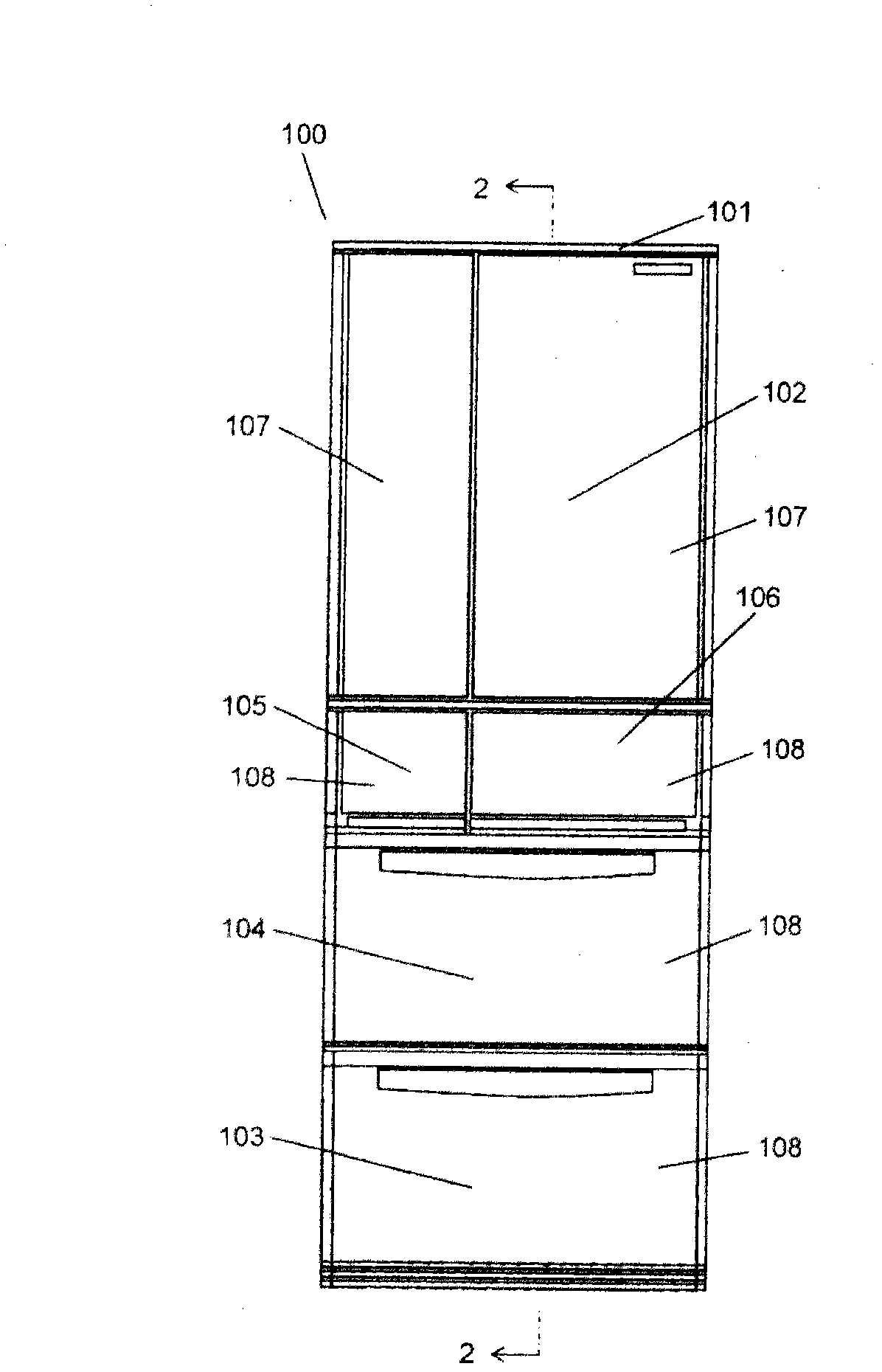
[0057] figure 1 It is a front view of the refrigerator in Embodiment 1 of this invention. Such as figure 1 As shown, refrigerator 100 according to Embodiment 1 of the present invention is refrigerator 100 equipped with side-by-side doors, and a plurality of divided storage rooms are provided in heat insulating box 101 . The storage room is called a refrigerating room 102, an ice making room 105, a switching room 106, a vegetable room 104, a freezing room 103, etc. according to its function (cooling temperature).
[0058] A rotary insulating door 107 filled with a foam heat insulating material such as polyurethane is provided in the front opening of the refrigerator compartment 102 . In addition, in the ice making room 105, the switch room 106, the vegetable room 104, and the freezer room 103, heat insulating boards 108 as front plates of drawers are provided respectively, so that the storage rooms are sealed so that cold air does not leak out.
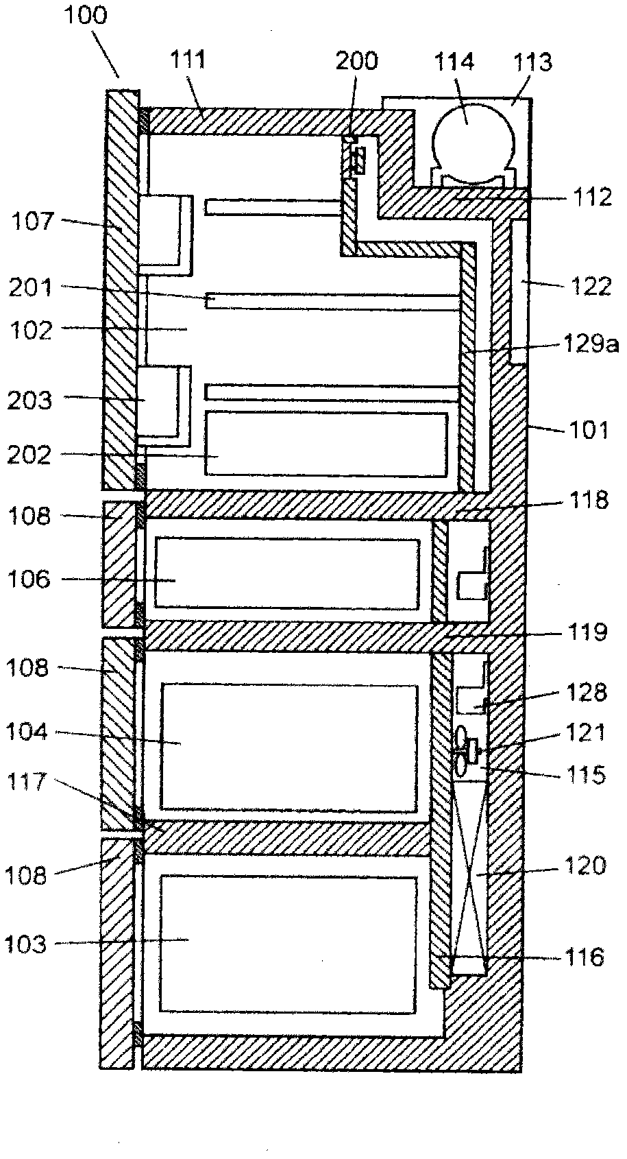
[0059] figure 2 It is a ...
Embodiment approach 2
[0147] As described above, Embodiment 1 has been described around making the temperature distribution of the refrigerator compartment uniform based on the positional relationship between the discharge port and the suction port (both the discharge port and the suction port are provided on the duct side).
[0148] However, as a method of making the temperature distribution of the refrigerating room uniform, it has been found through careful examination that the modified example has a certain effect in practical use, and it will be described below.
[0149] Embodiment 2 will be described below as a first modified example. Embodiment 2 of the present invention differs from Embodiment 1 in that instead of the right discharge ports 130e and 130f, the left discharge ports 130a and 130b are provided.
[0150] Figure 16 It is explanatory drawing of the duct with which the refrigerator in Embodiment 2 of this invention is equipped. Here, when the door of refrigerating room 102 is ope...
Embodiment approach 3
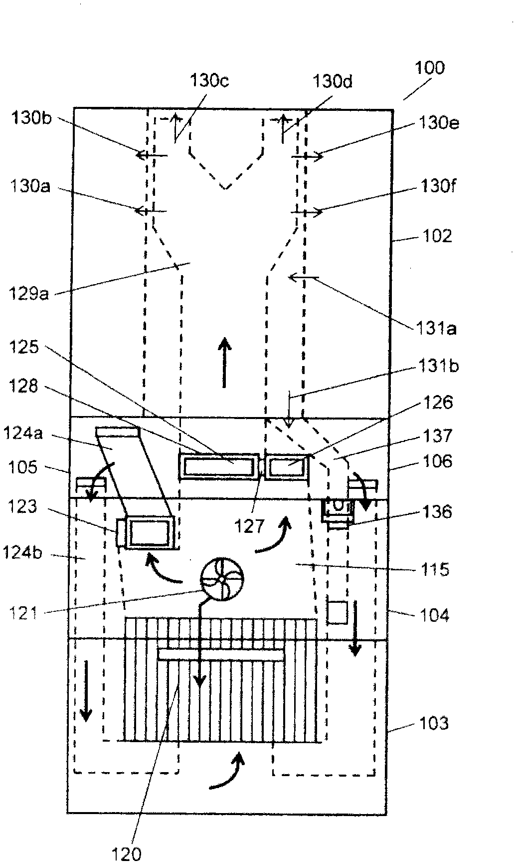
[0171] Next, Embodiment 3 will be described as a second modified example. Embodiment 3 of the present invention differs from Embodiment 1 in that the discharge ports 130a, 130b, 130e, and 130f are not provided on the side of the duct 129a, but are provided on the front of the duct 129a.
[0172] Figure 17 It is explanatory drawing of the duct with which the refrigerator in Embodiment 3 of this invention is equipped. Here, when the door of refrigerator compartment 102 is opened, the part visible from the front is shown. That is, the duct 129a is provided along the heat insulation box 101 of the refrigerating room 102 adopting the heat insulation structure, and a Y-shaped cold air circulation path is formed between the duct 129a and the heat insulation box 101 . Such as Figure 17 As shown by the arrows in the refrigerator compartment 102, the cold air in the refrigerator compartment 102 is sucked from the suction port 131a opened below the refrigerator compartment 102, circ...
PUM
 Abstract
Description
Claims
Application Information
 - R&D Engineer
- R&D Manager
- IP Professional
- Industry Leading Data Capabilities
- Powerful AI technology
- Patent DNA Extraction
Browse by: Latest US Patents, China's latest patents, Technical Efficacy Thesaurus, Application Domain, Technology Topic, Popular Technical Reports.
© 2024 PatSnap. All rights reserved.Legal|Privacy policy|Modern Slavery Act Transparency Statement|Sitemap|About US| Contact US: help@patsnap.com