Supercharge Your Innovation With Domain-Expert AI Agents!

Injection mold with movement core insert stopping mechanism

A technology for injection molds and male mold cores, which is applied in the field of injection molds and mold manufacturing. It can solve problems that affect the appearance of products, burrs, and PL surfaces that are not tightly closed, and achieve the effects of broad application prospects, improved appearance and yield rate

Inactive Publication Date: 2011-08-17
KAEDAR ELECTRONICS KUNSHAN
View PDF2 Cites 2 Cited by
  • Summary
  • Abstract
  • Description
  • Claims
  • Application Information

AI Technical Summary

Problems solved by technology

[0003] The production molds for the above-mentioned types of products usually adopt the structural method of oblique core pulling, but the disadvantage of this method is that the moving male mold core (big oblique drawing) will retreat due to excessive injection pressure, which will cause the PL surface to not close tightly. , thus forming burrs and affecting the appearance of the product, so it is necessary to consider improving the design of the mold itself to solve the above problems

Method used


Image

  • Injection mold with movement core insert stopping mechanism
  • Injection mold with movement core insert stopping mechanism
  • Injection mold with movement core insert stopping mechanism

Examples


specific Embodiment approach

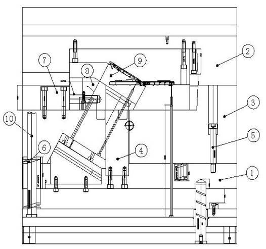
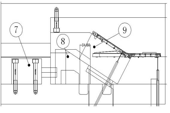
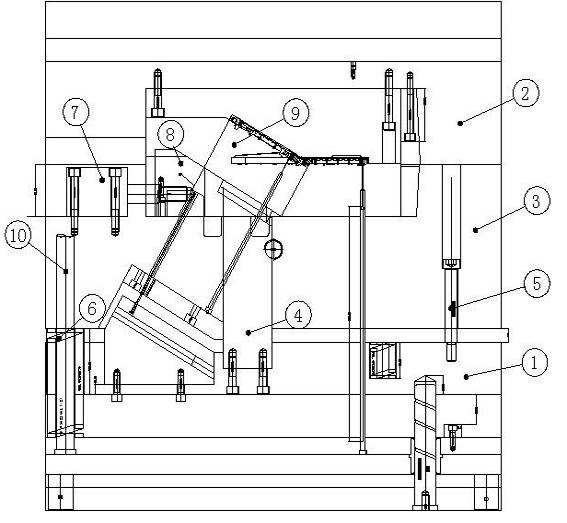
[0020] figure 1 It is the front view of the mold closed state of the present invention.

[0021] Such as figure 1 Shown: an injection mold with a movement male mold core stop mechanism, including a movable mold carrier plate 1, a movable mold plate 3, a fixed mold plate 2, a movable male mold core 9 and a bundle block 4. Among them, the fixed mold plate 2 and the movable mold plate 3 are opposite The movable male mold core 9 is set in the cavity formed by the cooperation of the fixed mold plate 2 and the movable mold plate 3. The movable mold bearing plate 1 is located at the lower part of the movable mold plate 3, and is connected with the movable mold plate 3 by equal height screws 5. The movable mold plate 3 The moving distance of is determined by the equal height screw 5, which plays a role of control, and the spring 6 arranged between the movable template 3 and the movable mold bearing plate 1 supports the movable template 3. In addition, the bundle block 4 is fixed on the m...


PUM


Abstract

The invention discloses an injection mold with a movement core insert stopping mechanism, comprising a movable mold bearing plate, a movable mold plate, a fixed mold plate, a movable core insert and a binding block, wherein the fixed mold plate and the movable mold plate are arranged oppositely, and are matched to form a die cavity; the movable core insert is arranged in the die cavity; the movable mold bearing plate is positioned at the lower part of the movable mold plate, and is connected with the movable mold plate through screws which are equal in height; the binding block is fixed on the movable mold bearing plate, and the binding block penetrates through the movable mold plate; besides, a movement core insert stopping mechanism is arranged at one side of the upper surface of the movable mold plate; the movement core insert stopping mechanism comprises a driving device and a stopping guide rod; the driving device is fixed on the movable mold plate; the end face of the stopping guide rod connected with the driving device is provided with an inclined surface; and the inclined surface is matched with the inclined surface of the movable core insert. The injection mold in the invention uses the movement core insert stopping mechanism for guaranteeing the safety of the action of the mold, eliminating the gap between PL surfaces, improving the appearance and yield of the products, and covering the shortages of the inclined core-extracting way of the mold; and the injection mold has a wide application prospect.

Description

Technical field [0001] The invention relates to a mold, in particular to an injection mold with a moving mold core stopping mechanism, and belongs to the technical field of mold manufacturing. Background technique [0002] At present, many plastic products are processed by mold injection molding. In the injection molding process of some structurally more complex products, a good mold structure is mainly used to ensure the product yield and the safety of the mold itself. [0003] The production molds for the above-mentioned types of products usually adopt the structure method of oblique core pulling, but the disadvantage of this method is that the moving male mold core (oblique pulling large into the child) retreats due to excessive injection pressure, which causes the PL surface to not be tightly closed. , Thus forming burrs, affecting the appearance of the product, so we need to consider the design improvement of the mold itself to solve the above-mentioned problems. Summary of t...

Claims


Application Information

Patent Timeline
Patent Type & Authority Applications(China)
IPC IPC(8): B29C45/26
Inventor 李明顺朱昭宇韦华军
Owner KAEDAR ELECTRONICS KUNSHAN
Features
  • R&D
  • Intellectual Property
  • Life Sciences
  • Materials
  • Tech Scout
  • Unparalleled Data Quality
  • Higher Quality Content
  • 60% Fewer Hallucinations
Learn More