Cabinet lock control structure

A cabinet and lock technology, applied in cabinets, chests of drawers, building locks, etc., can solve the problems of increasing the height of the cabinet and increasing the cost of the cabinet 7, and achieve the effect of smooth movement

Inactive Publication Date: 2011-08-24
张庭瑜
View PDF4 Cites 4 Cited by
  • Summary
  • Abstract
  • Description
  • Claims
  • Application Information

AI Technical Summary

Problems solved by technology

[0005] However, in the aforementioned existing cabinet locking control device, since the locking bar 92 is arranged at the top position of the cabinet, when the height of the cabinet 7 is high, the user cannot easily twist and lock the locking bar. 92 actions of the lock head 93; and if the lock bar 92 is directly set in the central position of the cabinet body 7 to facilitate the user's operation, then it is necessary to reserve a space for the lock bar 92 between the drawer and the drawer. As a result, not only the cost of the cabinet body 7 will be increased, but also the height of the cabinet body will be increased.
[0006] Therefore, the existing cabinet lock control device still has not reached perfection and can be improved. Accordingly, the inventor is relying on many years of experience in related industries, and after continuous hard thinking and trial production, finally developed the invention

Method used


Image

  • Cabinet lock control structure
  • Cabinet lock control structure
  • Cabinet lock control structure

Examples


Embodiment Construction

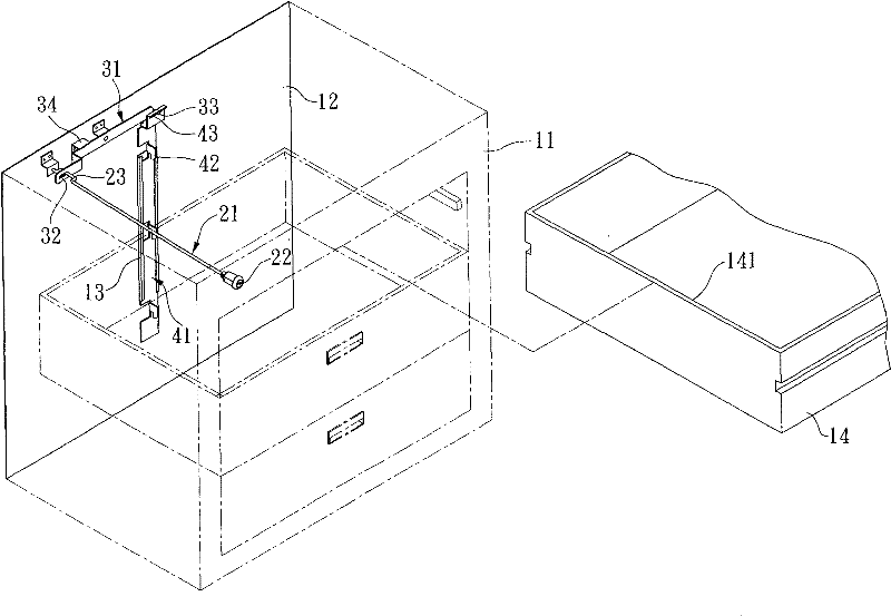
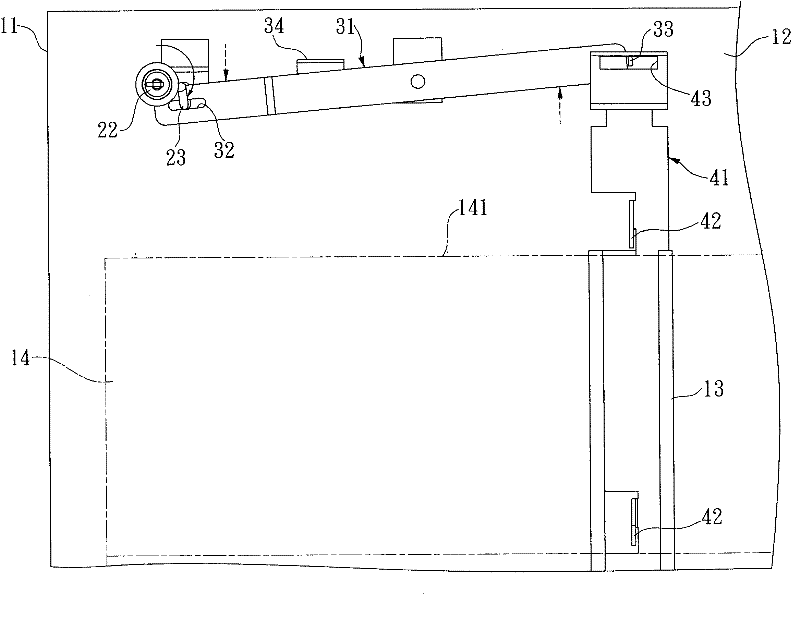
[0032] See first figure 1 and figure 2 , is the first embodiment of a cabinet lock control structure provided by the present invention, which is mainly composed of a cabinet body 11, a transmission part 21, an action part 31 and a limiting part 41, wherein:

[0033] The cabinet body 11 is hollow, and a rail 13 extending longitudinally is provided on an inner wall surface 12 of the cabinet body 11, and several drawers 14 are provided inside the cabinet body 11, and each drawer 14 faces the rail 13 One side of is defined as a hooking side 141 .

[0034] The transmission member 21 is a transmission rod in this embodiment, and one end of the transmission member 21 is pivotally connected to the inner wall surface 12 of the cabinet body 11 on the side where the track 13 is provided, while the other end of the transmission member 21 is It is connected with a lock head 22 provided on the outer wall of the cabinet body 11, and is bent to form a "ㄇ" shaped transmission part 23 near ...


PUM


Abstract

A cabinet lock control structure includes a cabinet body, which has a track arranged on the internal face and is passed through by a plurality of drawers; a transmission member, arranged inside the cabinet body; a transmission portion, which is formed on one end of the transmission member; an action member, which is pivotally arranged on the track-arranged internal face of the cabinet body; a motion aperture, which is arranged on one end of the action member; a motion portion, which is arranged on the other end of the action member; and a restriction member, which is slideably arranged in thetrack and has a hook portion to lock the drawers by hooking. Besides, the transmission portion of the transmission member passes through and is pressed against the motion aperture of the action member. When the driving member rotates, the transmission portion pushes the action member to the top to perform a swing movement. Further, the restriction member is connected with the motion portion of the action member so that the restriction member,linked to the action member, shifts up and down along the track when the action member swings, thereby to control the locking states of the drawers.

Description

technical field [0001] The invention relates to a cabinet lock control structure. Background technique [0002] Existing cabinet locking devices, such as Figure 12 As shown, it includes a cabinet body 7 and an accommodating space 71 located in the cabinet body 7. The accommodating space 71 has an opening 72 on the side edge of the cabinet body 7, and the opening 72 is used for passing through Several drawers 8 arranged up and down. The vacant space 71 is provided with a slideway group 731 on a wall surface 73 away from the opening 72, and a clamping rod 9 is slid inside the slideway group 731, and the clamping rod 9 is equidistantly provided with several clamping holes 91. , and the clamping lever 9 is pivoted by a locking lever 92 to slide in linkage. [0003] Wherein, one end of the lock bar 92 is connected with a lock head 93, and the lock head 93 is arranged on the side edge of the cabinet body 7 adjacent to the opening 72, and the other end of the lock bar 92 is pass...

Claims


Application Information

Patent Timeline
Patent Type & Authority Applications(China)
IPC IPC(8): A47B67/04E05B65/46E05B65/462
Inventor 张庭瑜
Owner 张庭瑜
Why Eureka
Try Eureka