
Method and device for detecting state of overcurrent protector of battery

The technology of a state detection device and an overcurrent protector is applied in the electrical field, which can solve the problems of misjudgment and low reliability, and achieve the effect of reducing the detection cost.

Active Publication Date: 2011-08-24
ZTE CORP
View PDF7 Cites 7 Cited by
  • Summary
  • Abstract
  • Description
  • Claims
  • Application Information

AI Technical Summary

Benefits of technology

This technology helps quickly identify if an electronic device's power source has trouble or needs maintenance without having it be taken offline for testing purposes. It uses this detected signal from another part called the current sensor that measures how much electricity flows through its terminals when connected to other parts like batteries. By doing these measurements with different voltages at both ends of each component, we are able to predict whether they should stop working properly before any damage occurs due to excessive electrical currents flowing into them during normal use.

Problems solved by technology

This technical problem addressed in this patents relates to improving the reliability and efficiency of detecting excessive current (I) flow through batteries during normal use conditions such as under heavy loads.

Method used


Image

  • Method and device for detecting state of overcurrent protector of battery
  • Method and device for detecting state of overcurrent protector of battery
  • Method and device for detecting state of overcurrent protector of battery

Examples


Embodiment Construction

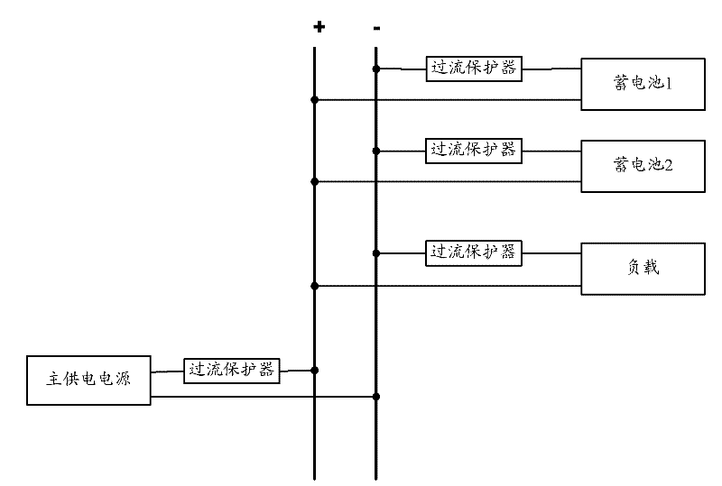
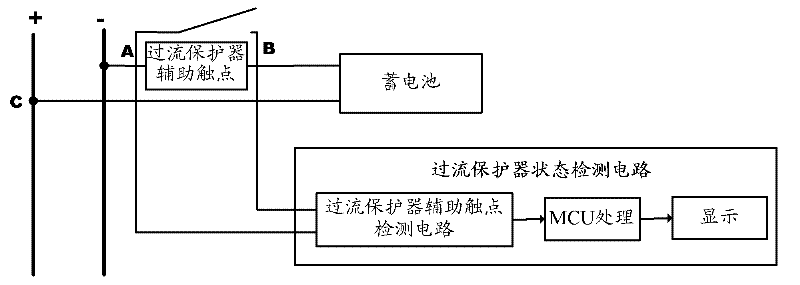
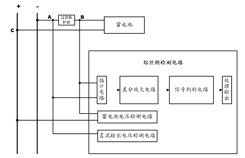
[0036] In order to solve the problem of low reliability or misjudgment in the prior art when judging the state of the overcurrent protector, the present invention provides a method and device for detecting the state of the battery overcurrent protector. The invention is described in further detail. It should be understood that the specific embodiments described here are only used to explain the present invention, not to limit the present invention.

[0037] Such as Figure 4 , 5 As shown, the present invention relates to a method for detecting the state of a battery overcurrent protector, comprising the following steps:

[0038] Step S101, obtaining the voltage U of the power supplyout , and the voltage U of the battery connected to the power supply through the overcurrent protector bat , and calculate the difference U between the power supply voltage and the battery voltage, namely: U=|U out -U bat |;

[0039] Step S102, firstly, the minimum value U of the difference be...


PUM


Abstract

The invention discloses a method and a device for detecting a state of an overcurrent protector of a battery. The method comprises the following steps of: acquiring voltage Uout of a power supply source, and voltage Ubat of the battery connected with the power supply source via the overcurrent protector, and calculating U, wherein U is equal to the absolute value of Uout minus Ubat; when U is more than or equal to UL and less than or equal to UH, and the absolute value of Ibat is less than or equal to Imin, adjusting the voltage of the power supply source to be U'out, wherein UL is the minimum value of a difference value between the voltage of the power supply source and the voltage of the battery, UH is the maximum value of the difference value between the voltage of the power supply source and the voltage of the battery, Ibat is a current value of the battery and Imin is a current detection precision value of equipment for detecting the current of the battery; acquiring the voltage of the battery U'bat after the voltage of the power supply source is adjusted, and calculating U', wherein U' is equal to an absolute value of U'out minus U'bat; and judging the state of the overcurrent protector of the battery according to a relation of U' and UH. By the invention, in case of a smaller difference value between the voltage of the battery and the voltage of the power supply, the state of the overcurrent protector of the battery can be precisely detected by adjusting the voltage of the power supply and comparing the difference value between the voltage at two ends of the overcurrent protector again, and the detection cost can be lowered.

Description


Claims


Application Information

Patent Timeline
Owner ZTE CORP
Learn More