Method and circuit for detecting working condition of relay in high voltage loop of electric automobile

A high-voltage circuit, working state technology, used in circuit breaker testing, current/voltage measurement, instruments, etc., can solve problems such as inaccurate detection and real-time monitoring, to avoid safety accidents, reduce failure risks, and ensure The effect of safety features

Active Publication Date: 2013-06-12
奇瑞新能源汽车股份有限公司
View PDF1 Cites 0 Cited by
  • Summary
  • Abstract
  • Description
  • Claims
  • Application Information

AI Technical Summary

Problems solved by technology

[0005] The shortcomings of this case are: 1. The current detection is greatly affected by external factors. It can only be detected when the power battery pack is charging and discharging, and cannot be monitored in real time; 2. The method of current detection can only detect The relay is faulty, but it cannot accurately detect whether the positive relay or the negative relay is faulty

Method used


Image

  • Method and circuit for detecting working condition of relay in high voltage loop of electric automobile
  • Method and circuit for detecting working condition of relay in high voltage loop of electric automobile
  • Method and circuit for detecting working condition of relay in high voltage loop of electric automobile

Examples


Embodiment 1

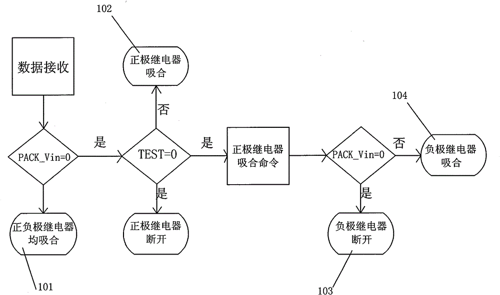
[0026] This embodiment provides a method for detecting the working state of a relay in a high-voltage circuit of an electric vehicle, which collects the voltage at both ends of the positive relay and the negative relay respectively, and collects the voltage at both ends of the battery pack. Determine the working status of the positive and negative relays.

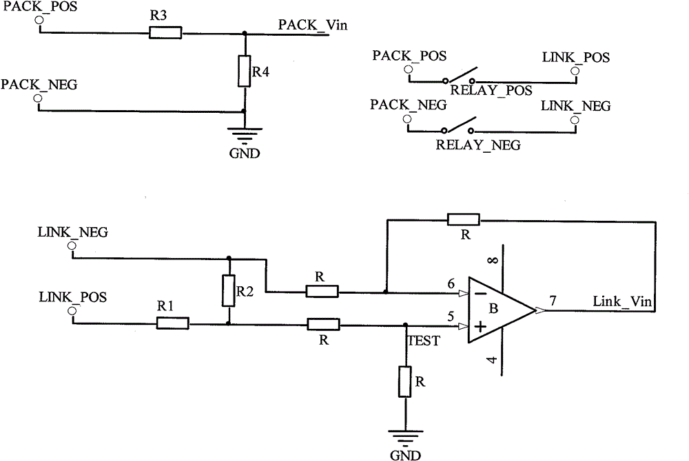
[0027] The method for collecting the voltage at both ends of the positive relay and the negative relay specifically includes: connecting the output terminals of the positive relay and the negative relay to the input terminal of the operational amplifier, wherein the positive relay is connected to the non-inverting input terminal of the operational amplifier, and the negative relay is connected to the input terminal of the operational amplifier. The inverting input terminal, and the voltage value Link_Vin is collected at the output terminal of the operational amplifier and the voltage value TEST is collected at the non-invert...

Embodiment 2

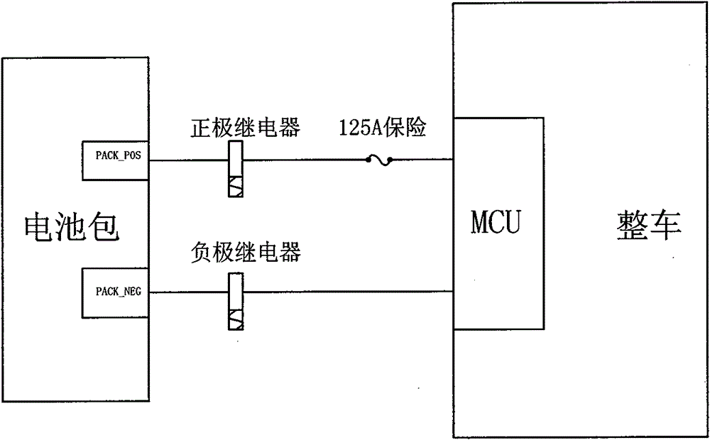
[0035] This embodiment provides a device for detecting the working state of a relay in a high-voltage circuit of an electric vehicle, as shown in the attached image 3 As shown, the circuit includes the positive pole PACK_POS of the battery pack, the negative pole PACK_NEG of the battery pack, the positive relay output terminal LINK_POS, and the negative relay output terminal LINK_NEG, wherein a positive relay RELAY_POS is connected in series between the positive pole PACK_POS of the battery pack and the positive relay output terminal LINK_POS. A negative relay (RELAY_NEG) is connected in series between the negative pole PACK_NEG and the negative relay output terminal LINK_NEG.

[0036]The battery pack voltage acquisition point PACK_Vin is set between the positive pole PACK_POS of the battery pack and the negative pole PACK_NEG of the battery pack; the output terminal LINK_POS of the positive relay and the output terminal LINK_NEG of the negative relay are connected to the oper...


PUM


Abstract

The invention relates to the field of a control circuit of an electric automobile, in particular to the control field of a relay in a high voltage loop, and provides a method and a circuit for detecting working conditions of the relay in the high voltage loop of the electric automobile. The method and the circuit for detecting the working condition of the relay in the high voltage loop of the electric automobile comprise the following steps of: collecting the voltage of a battery pack and the relay in the high voltage loop of the electric automobile, and judging the working conditions of an anode relay and a cathode relay according to the collected voltage values so as to provide the accurate working condition information of the relay to the driver, thereby achieving the safety protectionin the high voltage loop.

Description

technical field [0001] The invention relates to the field of control circuits of electric vehicles, especially the field of relay control in high-voltage circuits, and specifically provides a method and circuit for detecting the working state of relays in high-voltage circuits of electric vehicles. Background technique [0002] The current automobile market is gradually moving closer to energy saving and environmental protection, which makes hybrid electric vehicles, pure electric vehicles, plug-in hybrid electric vehicles, and fuel cell electric vehicles have a large market; and these models all have a major problem—— There is a high-voltage circuit in the vehicle control circuit, and the high-voltage circuit will bring safety hazards to users. Therefore, solving the safety protection of the high-voltage circuit has become the most important research object. [0003] as attached figure 1 As shown, it is the structural design of the high-voltage circuit in the electric vehi...

Claims


Application Information

Patent Timeline
Patent Type & Authority Patents(China)
IPC IPC(8): G01R31/327G01R19/00
Inventor 辛宏宇
Owner 奇瑞新能源汽车股份有限公司
Why Eureka
Try Eureka