
Fixing device and image forming apparatus

An image and toner image technology, which is applied in the field of image forming devices, can solve the problems of increasing the number of parts and not being able to realize miniaturization of image forming devices, etc.

Active Publication Date: 2013-10-23
KONICA MINOLTA BUSINESS TECH INC
View PDF4 Cites 0 Cited by
  • Summary
  • Abstract
  • Description
  • Claims
  • Application Information

AI Technical Summary

Problems solved by technology

[0009] However, the structure of the above-mentioned conventional fixing unit needs to provide the intermediate roller pair 504, so the number of parts increases correspondingly, the increase of manufacturing cost cannot be avoided, and the miniaturization of the image forming apparatus cannot be realized.

Method used


Image

  • Fixing device and image forming apparatus
  • Fixing device and image forming apparatus
  • Fixing device and image forming apparatus

Examples


Embodiment Construction

[0026] Hereinafter, embodiments of a fixing device and an image forming apparatus equipped with the fixing device according to the present invention will be described by taking a monochrome printer (hereinafter, simply referred to as a "printer") as an example.

[0027] (1) The overall structure of the printer

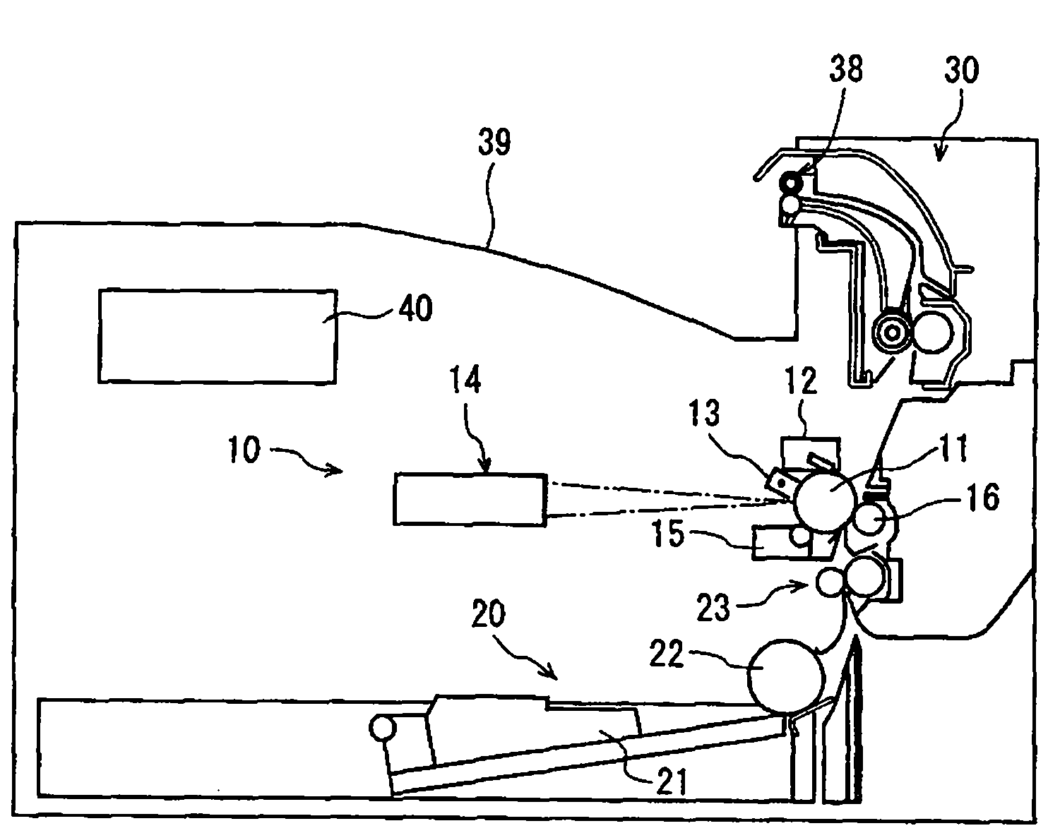
[0028] figure 1 It is a schematic diagram showing the overall configuration of the printer 100 according to this embodiment.

[0029] As above figure 1 As shown, the printer 100 is a printer that forms images by electrophotography, and includes an image forming unit 10 , a paper feeding unit 20 , a fixing unit 30 , and a control unit 40 .

[0030] The image forming unit 10 includes a photosensitive drum (drum) 11 , a cleaning unit 12 , a charger 13 , an exposure scanning unit 14 , a developing unit 15 , a transfer roller 16 , and the like.

[0031] In the image forming unit 10 , the peripheral surface of the photosensitive drum 11 is first cleaned by the cleaning ...


PUM


Abstract

A fixing device comprises: a heating rotary member and a pressurizing rotary member, which form a nip, and guiding members for guiding a recording sheet that has passed through the nip. In a cross-section perpendicular to a rotation axis of the heating rotary member, La connects axial centers of two rotary members, Lb is perpendicular to La, P is on a guiding surface of one of the guiding members and horizontally closer to the pressurizing rotary member than any other points thereon, said one of the guiding members being closer to the heating rotary member than the other, Lc passes through P and is tangent to an outer circumference of the heating rotary member near the nip, and D is a P-La distance. Here, heating rotary member diameter×1.6≦̸D<heating rotary member diameter×2.4. Above the nip, Lc leans further toward the heating rotary member than Lb, and 2.2°≦̸angle between Lc and Lb<6.5°.

Description

[0001] This application is based on Japanese application No. 2010-042057, the contents of which are hereby incorporated by reference. technical field [0002] The present invention relates to a fixing device provided with a guide member for suppressing occurrence of curl and wave of recording paper, and an image forming apparatus equipped with the fixing device. Background technique [0003] In recent years, the mainstream configuration of electrophotographic image forming apparatuses is to shorten the distance from the paper feeding port as much as possible by arranging the paper feeding port, the transfer position, and the fixing position on a substantially straight line in the longitudinal direction (the height direction of the device). The path to transfer, fixing, and discharge, thereby realizing the miniaturization of the main body of the device. [0004] However, in such an image forming apparatus having a vertical conveying path (hereinafter referred to as “vertical ...

Claims


Application Information

Patent Timeline
Patent Type & Authority Patents(China)
IPC IPC(8): G03G15/20G03G15/00
CPCG03G15/6573G03G15/2085G03G15/2028
Inventor 黑田胜良佐佐木龙之和田卓也岩月春树
Owner KONICA MINOLTA BUSINESS TECH INC
Features
  • Generate Ideas
  • Intellectual Property
  • Life Sciences
  • Materials
  • Tech Scout
  • Unparalleled Data Quality
  • Higher Quality Content
  • 60% Fewer Hallucinations
Learn More