
Matrix type touch panel and designing method thereof

A touch panel and design method technology, which is applied in computing, instrumentation, electrical digital data processing, etc., can solve the problems of touch point position deviation, affecting the linearity of the touch panel, and limited wiring accuracy.

Inactive Publication Date: 2011-08-31
WINTEK CORP +1
View PDF3 Cites 12 Cited by
  • Summary
  • Abstract
  • Description
  • Claims
  • Application Information

AI Technical Summary

Problems solved by technology

However, due to the limited precision of the traces produced by the process, the voltage of the touch panel at the same horizontal or vertical position is different, which affects the linearity of the touch panel, so that the detected touch point position will be different. Deviation

Method used


Image

  • Matrix type touch panel and designing method thereof
  • Matrix type touch panel and designing method thereof
  • Matrix type touch panel and designing method thereof

Examples


Embodiment Construction

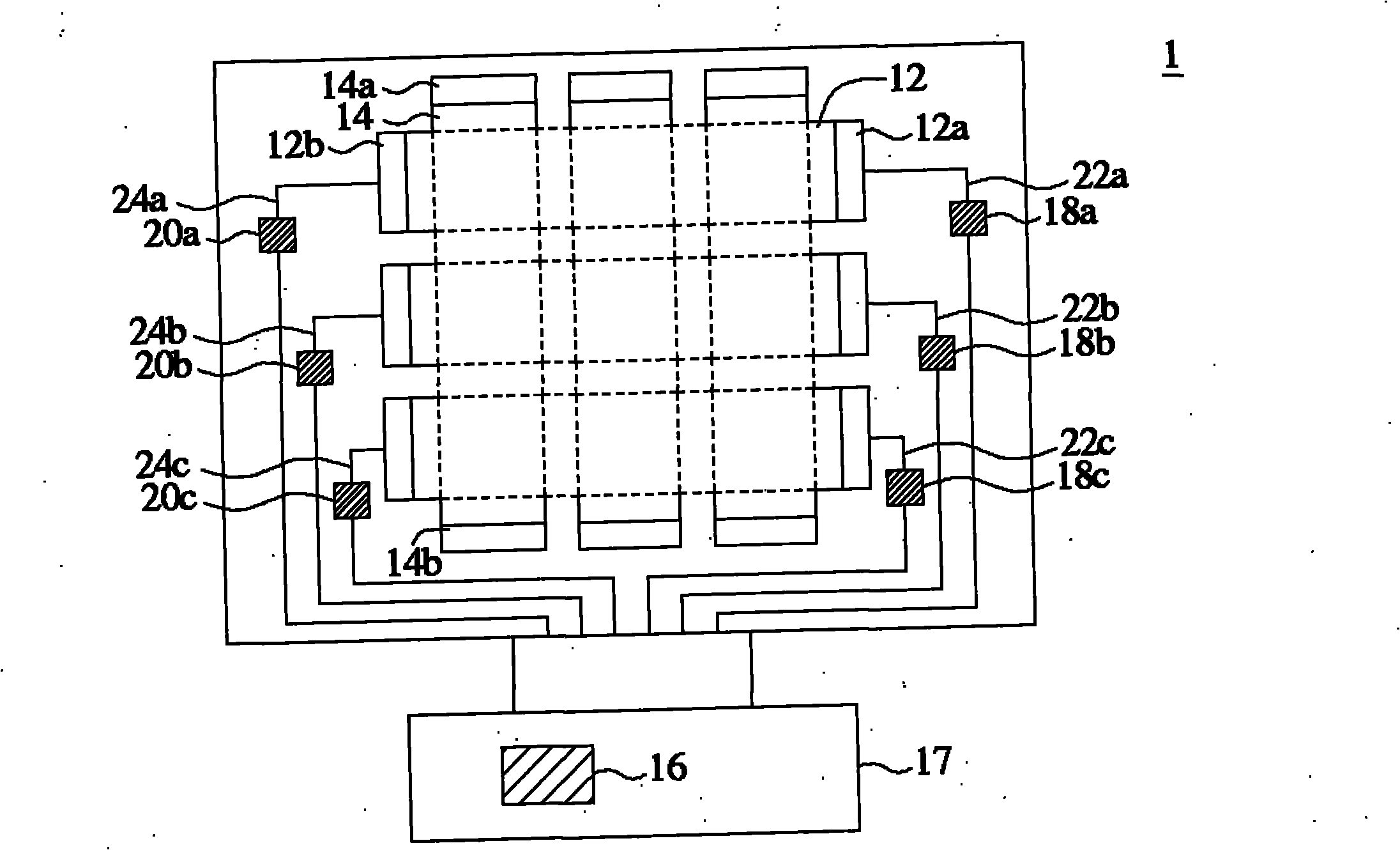
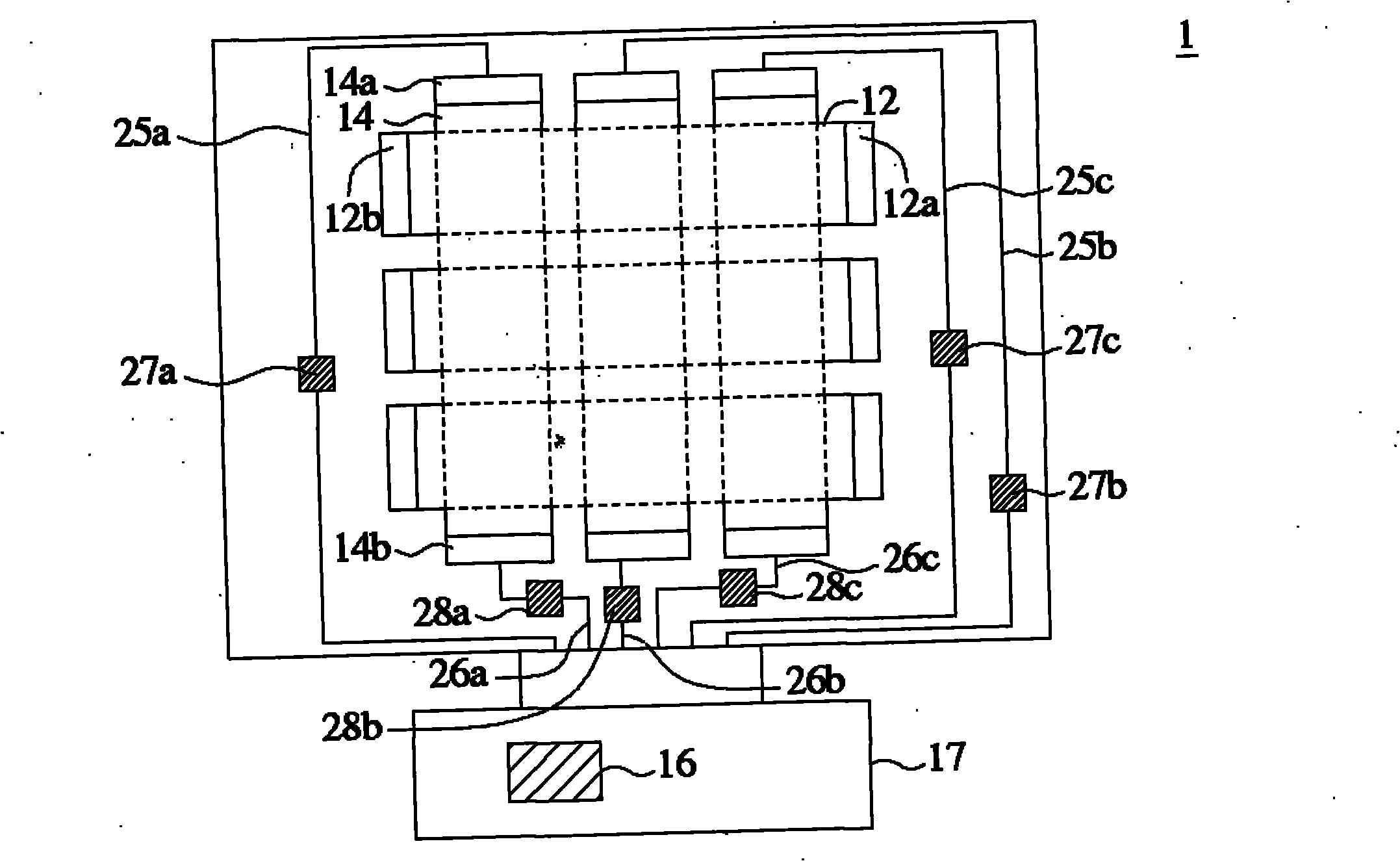
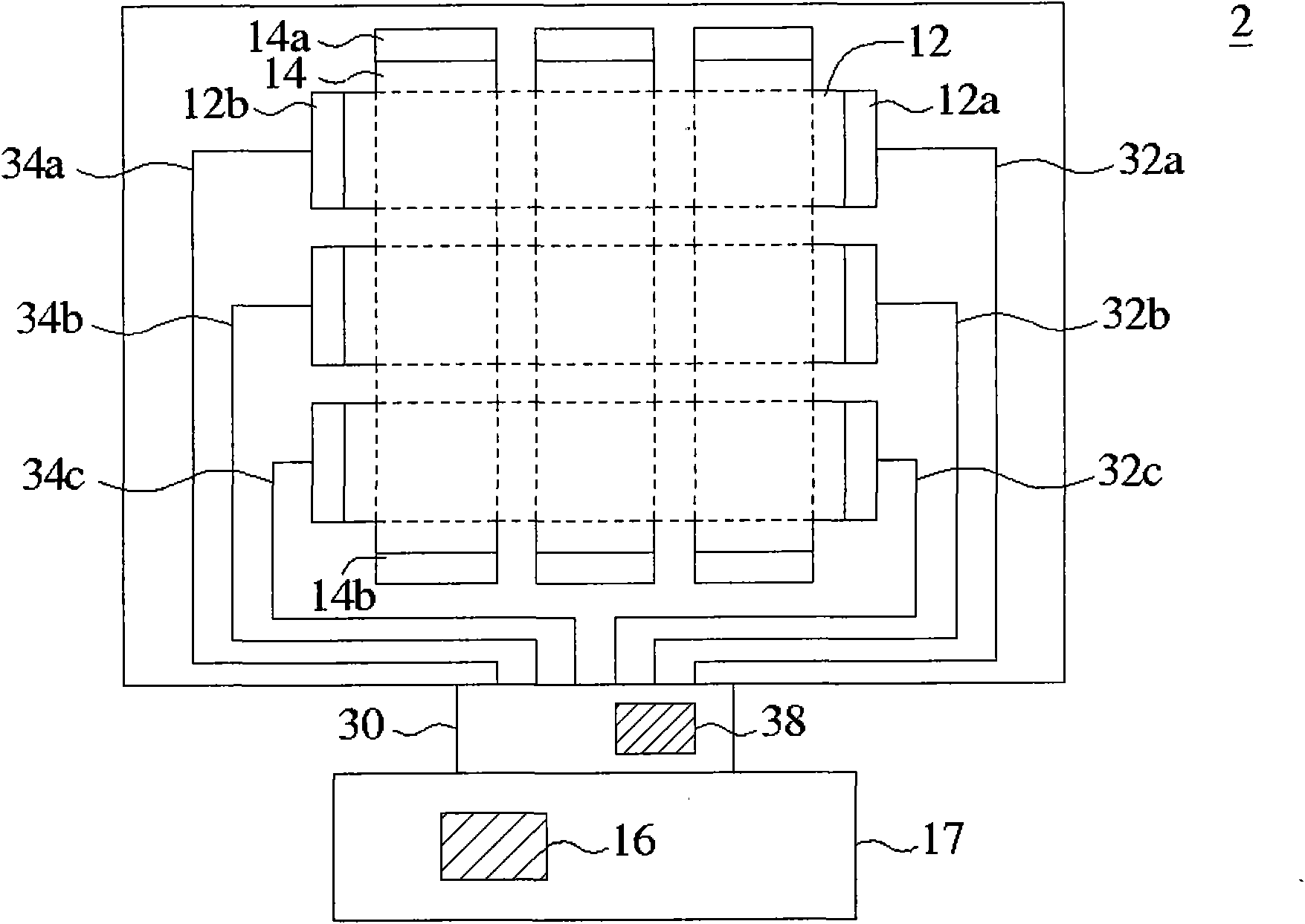
[0013] Please refer to Figure 1A , 1B , which is a schematic diagram of a matrix touch panel according to a preferred embodiment of the present invention. As shown in the figure, the matrix touch panel 1 includes a plurality of first sensing electrodes 12 , a plurality of second sensing electrodes 14 , a control circuit 16 and a compensation circuit. To simplify and clarify the schema, Figure 1A , 1B Only three of the first sensing electrodes 12 and the second sensing electrodes 14 are shown in the figure, and the configurations in which the first sensing electrodes 12 and the second sensing electrodes 14 are respectively connected to wires are shown in the two figures respectively. The first sensing electrodes 12 are arranged parallel to each other, for example extending along the horizontal direction of the drawing. Each of the first sensing electrodes 12 has a first end 12a and a second end 12b. The second sensing electrodes 14 are arranged parallel to each other, and ...


PUM


Abstract

The invention discloses a matrix type touch panel and a designing method thereof. The matrix type touch panel comprises a plurality of first sensing electrodes, a plurality of second sensing electrodes, a control circuit and a compensation circuit, wherein the first sensing electrodes are parallel with one another and provided with a first end and a second end respectively; the second sensing electrodes are parallel with one another; the extending direction of the second sensing electrodes is vertical to the extending direction of the first sensing electrodes; the second sensing electrodes are provided with a third end and a fourth end respectively; the compensation circuit is connected to the control circuit, the first and second ends of the first sensing electrodes and the third and fourth ends of the second sensing electrodes; and the compensation circuit is used for making a plurality of first impedance values from the first ends to the control circuit equal, making a plurality of second impedance values from the second ends to the control circuit equal, making a plurality of third impedance values from the third ends to the control circuit equal and making a plurality of fourth impedance values from the fourth ends to the control circuit equal.

Description

technical field [0001] The present invention relates to a touch panel, and in particular to a matrix touch panel and a design method thereof. Background technique [0002] Common touch technologies include, for example, capacitive touch and resistive touch. Recently, the matrix touch technology, which is improved from the general resistive touch technology, has the function of multi-touch because it can generate complete linear data. However, due to the limited precision of the traces produced by the process, the voltage of the touch panel at the same horizontal or vertical position is different, which affects the linearity of the touch panel, so that the detected touch point position will be different. produce deviations. Contents of the invention [0003] The invention relates to a matrix touch panel and a design method thereof, which improves the linearity of the panel by setting a compensation circuit. [0004] The present invention provides a matrix touch panel, wh...

Claims


Application Information

Patent Timeline
Patent Type & Authority Applications(China)
IPC IPC(8): G06F3/041G06F3/045
Inventor 林永常林明传林林林志强
Owner WINTEK CORP
Learn More