Upper drive vertical roll mill, mill layout and roll changing method

A vertical roller mill and transmission motor technology, which is applied in the direction of metal rolling mill stand, metal rolling stand, metal rolling, etc., can solve the problem of failure to change vertical rollers, difficult maintenance of lower transmission vertical roller mills, and Large and other problems, to achieve the effect of convenient roll change operation

Active Publication Date: 2015-10-14
CISDI ENG CO LTD +1
View PDF6 Cites 0 Cited by
  • Summary
  • Abstract
  • Description
  • Claims
  • Application Information

AI Technical Summary

Problems solved by technology

Under this compact layout requirement, if the vertical roll mill adopts the bottom drive type, there is no problem in realizing the compact layout of the multi-stand reversible continuous rolling mill, but the bottom drive vertical roll mill is not accepted by most users due to difficult maintenance; The traditional upper drive vertical roll mill, because the stand spacing is very tight, the vertical roll change cannot be achieved by the traditional roll change method (unless the stand spacing is increased)

Method used


Image

  • Upper drive vertical roll mill, mill layout and roll changing method
  • Upper drive vertical roll mill, mill layout and roll changing method
  • Upper drive vertical roll mill, mill layout and roll changing method

Examples


Embodiment Construction

[0041] Hereinafter, preferred embodiments of the present invention will be described in detail with reference to the accompanying drawings. It should be understood that the preferred embodiments are only for illustrating the present invention, but not for limiting the protection scope of the present invention.

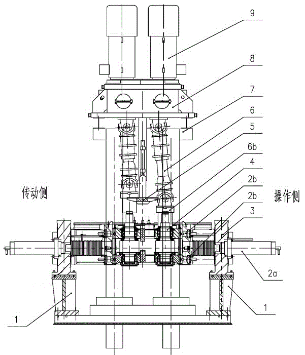
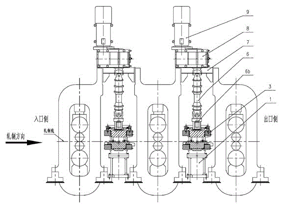
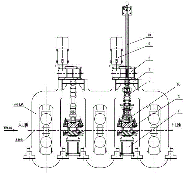
[0042] Such as figure 1 As shown, the upper drive vertical rolling mill of the present invention includes a base 1, a vertical roll frame 3 is arranged on the base 1, and vertical rolls 4 are installed on the vertical roll support 3.

[0043] The top of the vertical roller 4 is provided with a transmission bracket 7, and the transmission bracket 7 is provided with a transmission motor 9 and a speed reducer 8. The transmission motor 9 and the speed reducer 8 pass through the universal joint shaft 6, the flat head cover 6b of the universal joint shaft and the vertical roller Assembling 4 is connected, and the lower part of the reducer 8 is provided with a disengagement ...


PUM


Abstract

The invention discloses a novel upper-transmission vertical roller mill which comprises a base, wherein a vertical roller rack is arranged on the base; a vertical roller assembly is mounted on the vertical roller rack; a transmission bracket is arranged above the vertical roller assembly and located at the tops of stands of adjacent two apparatuses so as to support a transmission motor and a speed reducer; the transmission motor and the speed reducer are in transmission connection with the vertical roller through a universal coupling shaft; a separation mechanism is arranged between two universal coupling shafts below the speed reducer so as to separate the universal coupling shafts from the vertical roller; and the vertical roller rack is also provided with a side moving mechanism for the vertical roller to move along the two sides of the rack. The vertical roller mill disclosed by the invention can realize compact arrangement and quick roller change on the premise of adopting an upper-transmission vertical roller mill for multi-rack reversible tandem rolling; and the invention also discloses a novel mill arrangement mode and a roller changing method.

Description

technical field [0001] The invention relates to the technical field of rolling, in particular to an upper-drive vertical roll mill, and also relates to a more efficient rolling mill layout and a roll-changing method for the vertical roll mill. Background technique [0002] Vertical roll mills for medium and thick plates, steckel mills, hot continuous rolling and (or) flat steel engineering are used for rolling in the width direction of slabs, and the roll transmission types are divided into two types: upper transmission and lower transmission. The transmission device of the upper drive vertical roll mill is placed above the vertical roll frame, and the roll is driven by a vertically arranged universal joint shaft; the upper drive vertical roll mill has two types of roll change: fixed frame and frame moved out. The specific roll change The process is as follows: [0003] 1. The roller changing method of the frame-fixed upper transmission: [0004] 1. Move the roll assembly ...

Claims


Application Information

Patent Timeline
Patent Type & Authority Patents(China)
IPC IPC(8): B21B1/00B21B31/08
Inventor 王勇王勤李宏图熊建成余海蒋周强李晋李欣
Owner CISDI ENG CO LTD
Why Eureka
Try Eureka