
A collimated illumination system using an extended apparent source size to provide a high quality and efficient fixture

A technology of lighting system and size, applied in the direction of optical elements, light sources, electric light sources, etc. used to change the spectral characteristics of emitted light, can solve the problems of increasing optical loss, increasing manufacturing costs, and not being able to provide beam output, etc., to achieve a high degree of Beam collimation, improved uniformity effect

Active Publication Date: 2011-09-07
RADIANT RES
View PDF4 Cites 5 Cited by
  • Summary
  • Abstract
  • Description
  • Claims
  • Application Information

AI Technical Summary

Problems solved by technology

The use of such LED optical systems still does not provide good beam output, increases optical losses in the system (which is not satisfactory), and increases the manufacturing cost of such systems
Other issues with LED-based downlights include significant variations in CCT and CRI of the luminaire due to thermal management issues and binning of the LEDs
LEDs are significantly affected by temperature, and both light intensity and color light output may vary when operating temperature changes, making it difficult to maintain stable light intensity and color output
This variation in color and temperature is very unwelcome and makes it extremely difficult to match color or intensity across groups of luminaires
Recent improvements in LED coding still do not address these issues, making LED-based luminaires unattractive to consumers

Method used


Image

  • A collimated illumination system using an extended apparent source size to provide a high quality and efficient fixture
  • A collimated illumination system using an extended apparent source size to provide a high quality and efficient fixture
  • A collimated illumination system using an extended apparent source size to provide a high quality and efficient fixture

Examples


Embodiment Construction

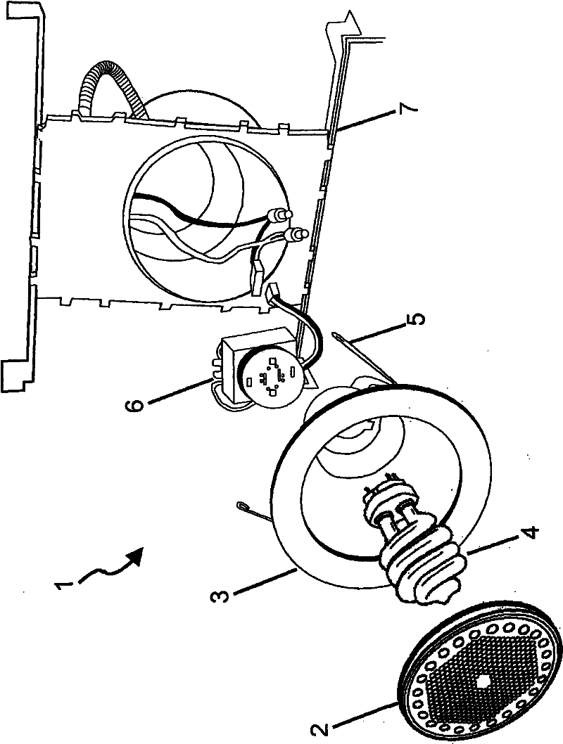
[0066] Figure 1 shows a prior art CFL downlight luminaire (1) comprising a diffuser (2) connected to a reflector (3) housing a CFL lamp (4) . The CFL (4) is connected to a CFL ballast (6) used to power the CFL lamp. The combined reflector (3), CFL lamp (4), diffuser (2) and CFL ballast (6) are attached and retained in the down-firing ceiling mount (7) using retaining clips (5). Such CFL downlight fixtures have very low LOR numbers, and because CFL lamps contain hazardous substances such as mercury, they are not environmentally friendly.

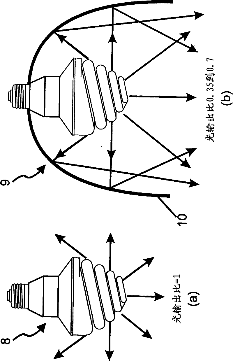
[0067] Figure 2(a) shows that the CFL lamp (8) emits light in an omnidirectional manner, so the light output ratio will be equal to 1 as a bulb alone. However, Figure 2(b) demonstrates that a CFL-based collimated downlight luminaire (9) utilizing a reflector (10) to collimate omnidirectional light from a CFL lamp becomes very inefficient, and for typical system light output ratios ranges from exactly 0.35 to a maximum of 0.7. It is import...


PUM

PropertyMeasurementUnit
power factoraaaaaaaaaa

Abstract

A downlighting illumination system (100) is provided having a high light output ratio with an extended apparent source size producing a near uniform illuminance, correlated colour temperature and colour rendering index distribution across an illuminated area. The system (100) includes a power source (61), an electronic driving system (60), a light emitting source (65), a reflector (67) arranged to receive light from the light emitting source (65) and to reflect light through an output aperture in a manner that virtually extends the apparent size of the light emitting source (65) to illuminate the output aperture.

Description

technical field [0001] This invention relates to improvements in downlighting lighting systems, and in particular to the use of such systems, but not exclusively to solid-state light sources such as light-emitting diodes (LEDs), which produce unwanted beam streaks, beam Consistency of color and intensity variations, and differences in correlated color temperature (CCT) and color rendering index (CRI) in system output. Background technique [0002] Downbeam lighting systems are used in a wide variety of structures for general lighting, task lighting, accent lighting, emergency lighting, hotel lighting, restaurant lighting, hospital lighting, office lighting, retail lighting, stairway lighting, and more. The vast majority of collimated downlighting systems are recessed in false or lowered ceilings, however variants can be recessed in walls or supported by frames attached to solid ceilings. Such beam-down systems are very desirable due to their flush-mounted assembly to the ce...

Claims


Application Information

Patent Timeline
Patent Type & Authority Applications(China)
IPC IPC(8): F21S8/02F21V21/04F21Y101/02
CPCF21S8/026F21Y2101/02F21V21/048F21V13/14F21V21/04F21V29/503F21Y2115/10F21V7/30F21V9/40
Inventor 杰弗里·霍华德·吉列特·阿兴霍尔德
Owner RADIANT RES
Learn More