
Rigid mill of screw rod

A powerful milling machine and screw technology, applied in the field of milling machines, can solve the problems that the turning depth and turning area cannot be increased, the work efficiency cannot be improved, and the turning force is small, so as to increase the turning force, increase the turning depth and turning area, and improve The effect of work efficiency

Inactive Publication Date: 2011-09-14
东莞泰星五金制品厂有限公司
View PDF4 Cites 6 Cited by
  • Summary
  • Abstract
  • Description
  • Claims
  • Application Information

AI Technical Summary

Problems solved by technology

[0003] When the existing milling machine is processing a large pitch, because the milling cutter on the tool holder is fixed, the turning force is too small during turning, and only one milling cutter can be installed on the tool holder, and the turning depth and turning area cannot be increased. , it usually requires repeated processing to process the required screw, and the work efficiency cannot be improved

Method used

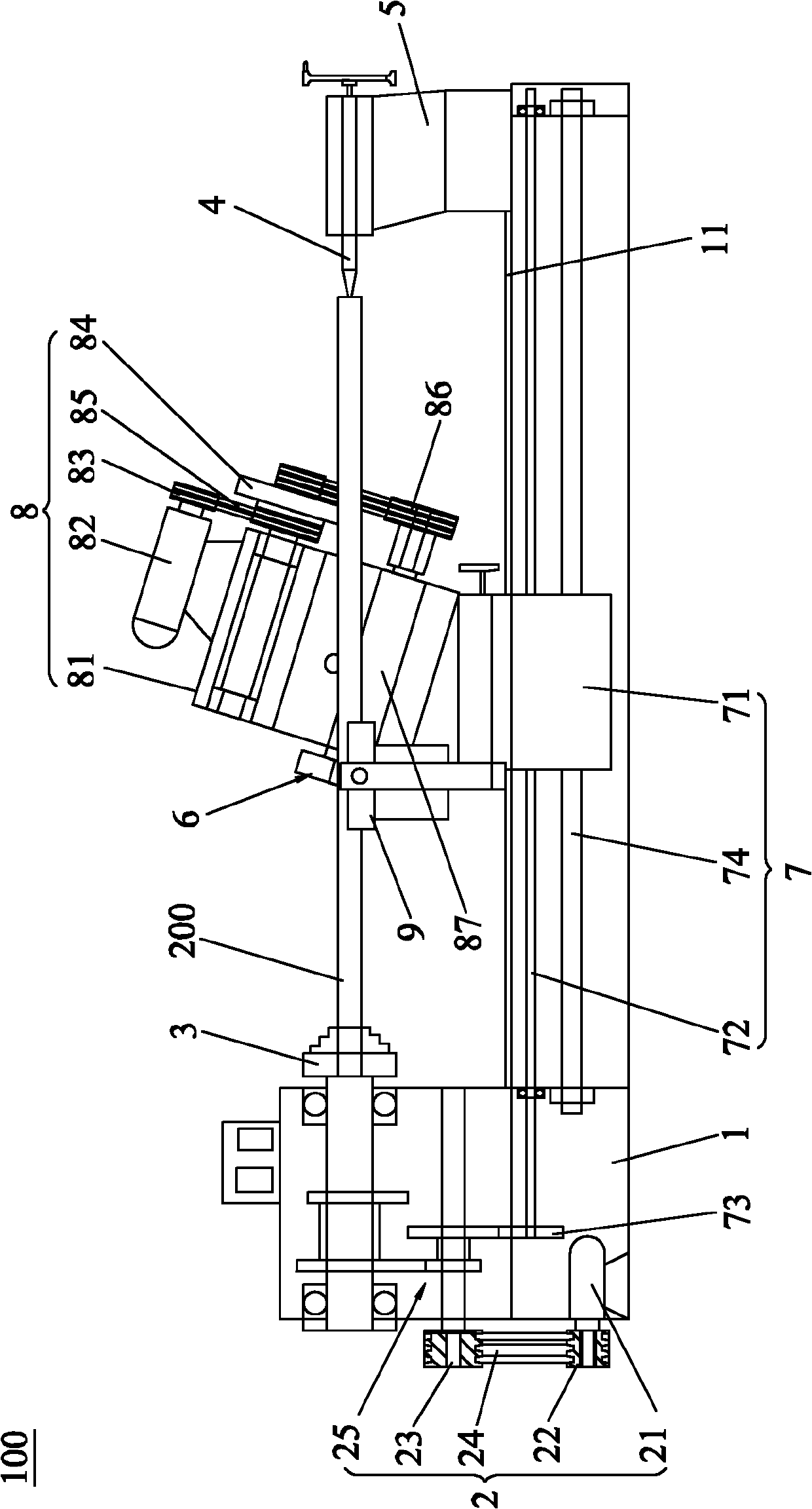
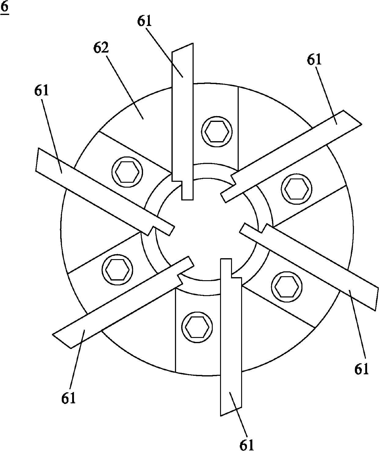
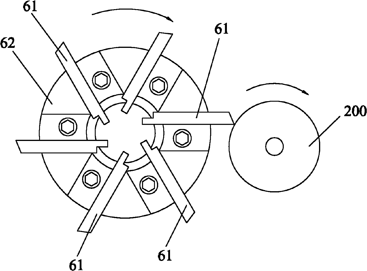

Image

  • Rigid mill of screw rod
  • Rigid mill of screw rod
  • Rigid mill of screw rod

Examples


Embodiment Construction

[0018] Such as figure 1 As shown, the screw powerful milling machine 100 of the present invention includes a machine tool body 1, a driving mechanism 2, a chuck 3, a thimble 4, a thimble holder 5, a milling head 6, a milling head moving mechanism 7, a milling head driving device 8, a chip removal channel 9 and control system (not shown). The driving mechanism 2 is installed on the machine tool body 1 and the output end is connected to the chuck 3 , the cylindrical workpiece 200 is placed horizontally, and the chuck 3 is clamped on the left end of the cylindrical workpiece 200 . The thimble 4 is installed on the thimble seat 5 and is in contact with the right end of the cylindrical workpiece 200. A slide rail 11 is provided on the machine tool body 1, and the thimble seat 5 is slidably mounted on the slide rail. 11, so that the thimble 4 and the chuck 3 can clamp cylindrical workpieces 200 of different lengths. The milling head moving mechanism 7 is movably mounted on the mac...


PUM


Abstract

The invention discloses a rigid mill of a screw rod, which is suitable for performing thread machining on a cylindrical workpiece. The rigid mill comprises a machine tool main body, a driving mechanism, a chuck, a thimble, a milling head, a milling head moving mechanism, a milling head driving device and a control system, wherein the driving mechanism is arranged on the machine tool main body, and the output end of the driving mechanism is connected with the chuck; the cylindrical workpiece is horizontally arranged; the chuck is clamped at the left end of the cylindrical workpiece; the thimble is arranged on the machine tool main body and is pressed against the right end of the cylindrical workpiece; the milling head moving mechanism is movably arranged on the machine tool main body; the milling head is connected with the output end of the milling head driving device and is provided with a plurality of milling cutters; the milling cutters are contacted with the surface of the cylindrical workpiece; the milling head driving device is arranged on the milling head moving mechanism; and the control system is electrically connected with the driving mechanism and the milling head driving device. The rigid mill of the screw rod has high turning force and high operating efficiency.

Description

technical field [0001] The invention relates to a milling machine, in particular to a screw powerful milling machine which is used for turning a screw and has large turning force and high working efficiency. Background technique [0002] A milling machine is a machine tool that uses a milling cutter to mill a workpiece to produce various surfaces. Usually the rotation of the workpiece is the main movement, and the movement of the milling cutter is the feed movement. It can process planes, grooves, threads, and various curved surfaces, gears, etc. For example, a screw milling machine generally clamps and places a cylindrical workpiece horizontally, then rotates the cylindrical workpiece through a driving mechanism, and processes threads on the surface of the cylindrical workpiece through the feed motion of the milling cutter. [0003] When the existing milling machine is processing a large pitch, because the milling cutter on the tool holder is fixed, the turning force is t...

Claims


Application Information

Patent Timeline
IPC IPC(8): B23C3/04B23C9/00
Inventor 吴春霖
Owner 东莞泰星五金制品厂有限公司
Learn More