Defrosting method of three-pipe heating recovery system

A heat recovery, three-pipe technology, applied in refrigerators, refrigeration components, refrigeration and liquefaction, etc., can solve the problems of extremely high safety requirements, slow defrosting speed, large power consumption, etc., and achieve small heating effect. , Improve the comfort of use and the effect of high defrosting efficiency

Inactive Publication Date: 2011-09-14
GD MIDEA HEATING & VENTILATING EQUIP CO LTD
View PDF5 Cites 9 Cited by
  • Summary
  • Abstract
  • Description
  • Claims
  • Application Information

AI Technical Summary

Problems solved by technology

[0002] In some low-temperature or high-humidity environments, frosting of the outdoor heat exchanger in the outdoor unit of the three-pipe heat recovery system is inevitable. There are several defrosting methods for the existing three-pipe heat recovery system: 1) Add an electric heating defrosting device to realize the defrosting effect through electric heating, but this method needs to add an electric heating device, which has high cost, high power consumption, and low efficiency. Extremely high; 2) There is only one outdoor heat exchanger, and the system switches the flow direction of the refrigerant, so that the outdoor heat exchanger originally used as an evaporator is transformed into a condenser, which uses the refrigerant to condense to release heat and melt the frost accumulated on the heat exchanger. But the disadvantage is that the switched indoor unit acts as an evaporator, which is equivalent to running the cooling mode, which runs counter to the user's needs; 3) Stop defrosting and let the frost melt naturally. Although this method is the most energy-saving, it is at the expense of The user's heating effect is the premise, and the outdoor ambient temperature is generally low when frosting occurs, the defrosting speed is slow, and the efficiency is very low

Method used


Image

  • Defrosting method of three-pipe heating recovery system
  • Defrosting method of three-pipe heating recovery system
  • Defrosting method of three-pipe heating recovery system

Examples


no. 1 example

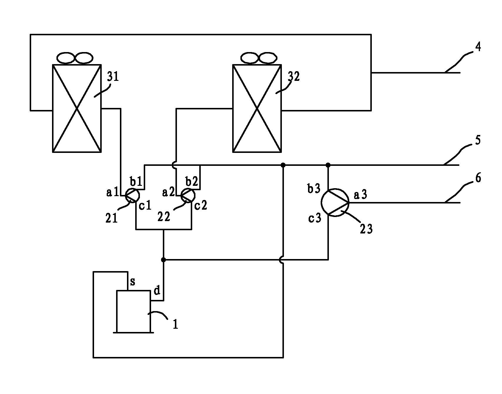
[0013] The defrosting method of the three-pipe heat recovery system, the outdoor unit of the three-pipe heat recovery system includes more than two outdoor heat exchangers, more than two three-way valves, more than one compressor, and high-pressure liquid pipes and low-pressure air pipes And the high-pressure air pipe, characterized in that in the heating mode or the mixed cooling and heating mode, when one of the outdoor heat exchangers is in the defrosting state of the condenser, the other outdoor heat exchanger must not be in the defrosting state of the condenser. During the defrosting process, the defrosting sequence of the outdoor heat exchanger can be adjusted arbitrarily according to the actual situation.

[0014] In heating mode or mixed cooling and heating mode, the outdoor heat exchanger is turned on successively and acts as a condenser for defrosting. The outdoor heat exchanger does not switch to condenser defrost at the same time. There is no limit to the number o...

no. 2 example

[0031] In this embodiment, the specific structure is the same as that of the first embodiment.

[0032] The following description will be made by taking defrosting as an example when both the first outdoor heat exchanger 31 and the second outdoor heat exchanger 32 are used as evaporators.

[0033] When the first outdoor heat exchanger 31 and the second outdoor heat exchanger 32 meet the set defrosting requirements, the first outdoor heat exchanger 31 first switches to condenser defrosting, and the second outdoor heat exchanger 32 maintains the original evaporation device status. After the first outdoor heat exchanger 31 completes the defrosting action, it switches back to the evaporator state, and at the same time, the second outdoor heat exchanger 32 switches to the condenser state for defrosting. After the second outdoor heat exchanger 32 completes the defrosting action , to switch back to the evaporator state. At this time, the two outdoor heat exchangers return to the or...

no. 3 example

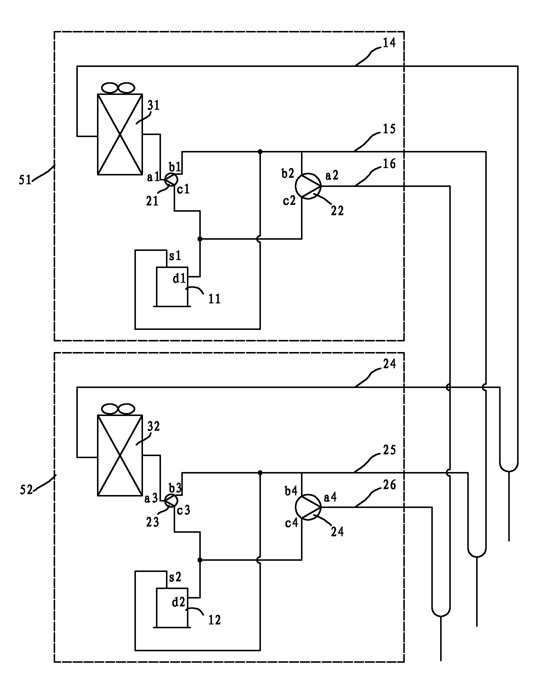
[0043] see figure 2 , the two-compressor structure of the three-pipe heat recovery system in this embodiment, the first outdoor unit 51 includes a first compressor 11, a first three-way valve 21, a second three-way valve 22, a first outdoor heat exchanger 31. The first high-pressure liquid pipe 14 , the first low-pressure air pipe 15 and the first high-pressure air pipe 16 .

[0044] The first discharge pipe d1 of the first compressor 11 is respectively connected to the third port c1 of the first three-way valve 21 and the third port c2 of the second three-way valve 22 .

[0045]The second port b1 of the first three-way valve 21 and the second port b2 of the second three-way valve 22 are respectively connected to the first low-pressure air pipe 15 and connected to the first air return pipe s1 of the first compressor 11 .

[0046] One end of the first outdoor heat exchanger 31 is connected to the first interface a1 of the first three-way valve 21 , and the other end of the fi...


PUM


Abstract

The invention discloses a defrosting method of a three-pipe heating recovery system. An outdoor unit of the three-pipe heating recovery system comprises more than two outdoor heat exchangers, more than two three-way valves, more than one compressor, a high-pressure liquid pipe, a low-pressure air pipe and a high-pressure air pipe; and in a heating mode or a mixed refrigerating/heating mode, one outdoor heat exchanger is in a condenser defrosting state, and the other outdoor heat exchanger is certainly not in a condenser defrosting state. In the defrosting process, the defrosting sequence of the outdoor heat exchangers can be adjusted at will according to the actual condition. In the defrosting method, the defrosting time of all the outdoor heat exchangers of the outdoor unit of the three-pipe heating recovery system is staggered, therefore, the capacity of an indoor machine for continuously supplying heat towards indoor is maintained, the influence on indoor heating effect is reduced, and the using comfort of an air conditioner is improved, so that the defrosting method achieves the characteristics of simpleness and flexibility for control, no need of additional electric-heating defrosting equipment, high defrosting efficiency, less influence on heating effect of the indoor unit in the defrosting period, and the like.

Description

technical field [0001] The invention relates to a three-pipe heat recovery system, in particular to a defrosting method for the three-pipe heat recovery system. Background technique [0002] In some low-temperature or high-humidity environments, frosting of the outdoor heat exchanger in the outdoor unit of the three-pipe heat recovery system is inevitable. There are several defrosting methods for the existing three-pipe heat recovery system: 1) Add an electric heating defrosting device to realize the defrosting effect through electric heating, but this method needs to add an electric heating device, which has high cost, high power consumption, and low efficiency. Extremely high; 2) There is only one outdoor heat exchanger, and the system switches the flow direction of the refrigerant, so that the outdoor heat exchanger originally used as an evaporator is transformed into a condenser, which uses the refrigerant to condense to release heat and melt the frost accumulated on the...

Claims


Application Information

Patent Timeline
Patent Type & Authority Applications(China)
IPC IPC(8): F25B47/02
Inventor 熊美兵许永锋马熙华冯明坤孙先金
Owner GD MIDEA HEATING & VENTILATING EQUIP CO LTD
Why Eureka
Try Eureka