Phase control for multiphase converter

A technology for converters and control signals, applied in control/regulation systems, instruments, DC power input conversion to DC power output, etc., can solve problems such as defective phase distribution, uneven phase switching, etc., and achieve a good phase distribution effect

Active Publication Date: 2011-09-14
CHENGDU MONOLITHIC POWER SYST
View PDF6 Cites 15 Cited by
  • Summary
  • Abstract
  • Description
  • Claims
  • Application Information

AI Technical Summary

Problems solved by technology

When the parameters of the two phases are different, the phase shift is not equal to 360 / 2=180 degrees, the phase switching is uneven, and the phase distribution is defective

Method used


Image

  • Phase control for multiphase converter
  • Phase control for multiphase converter
  • Phase control for multiphase converter

Examples


Embodiment Construction

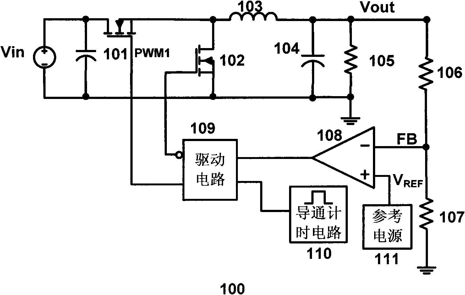
[0052] The disclosure below provides many different embodiments or examples to realize the technical solution provided by the present invention. Although components and arrangements of specific examples are described below, they are examples only and are not intended to limit the invention.

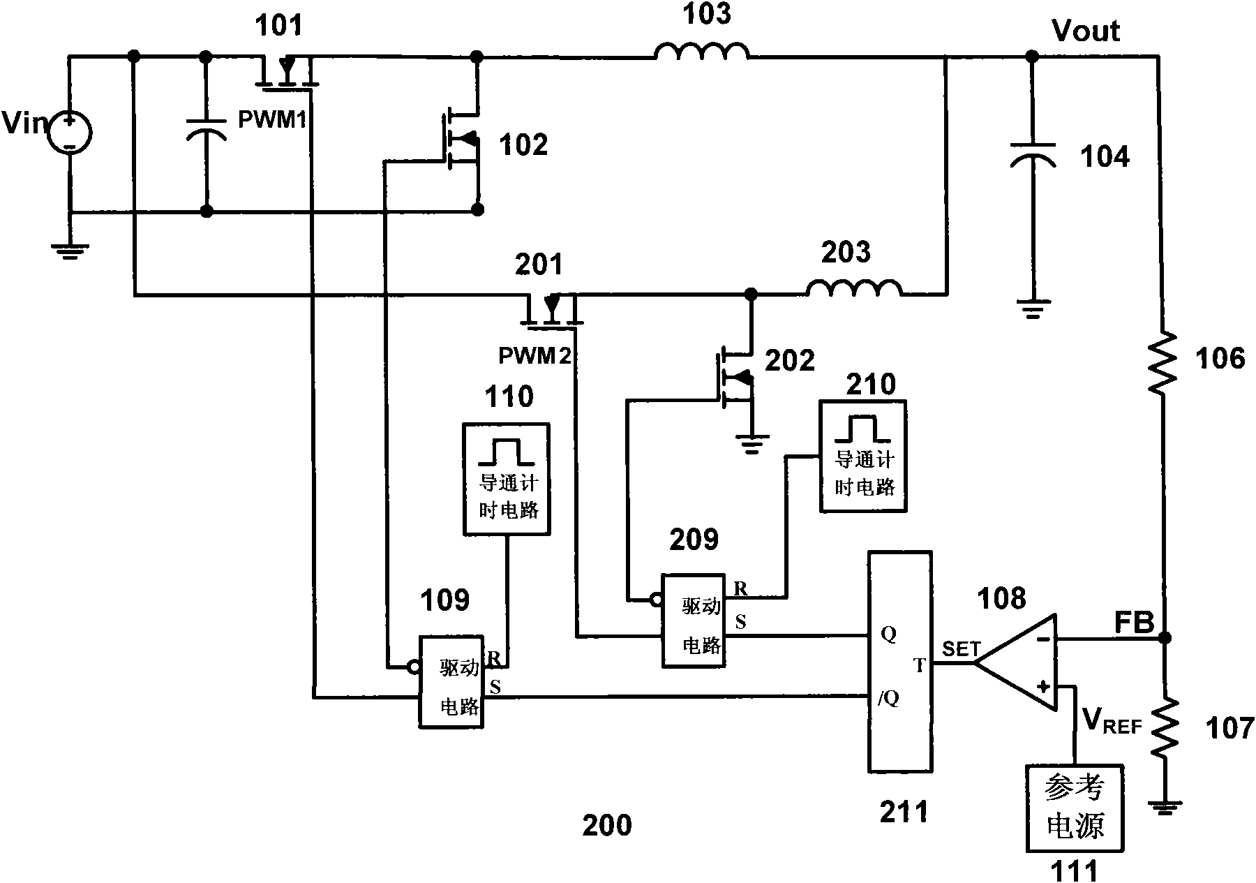
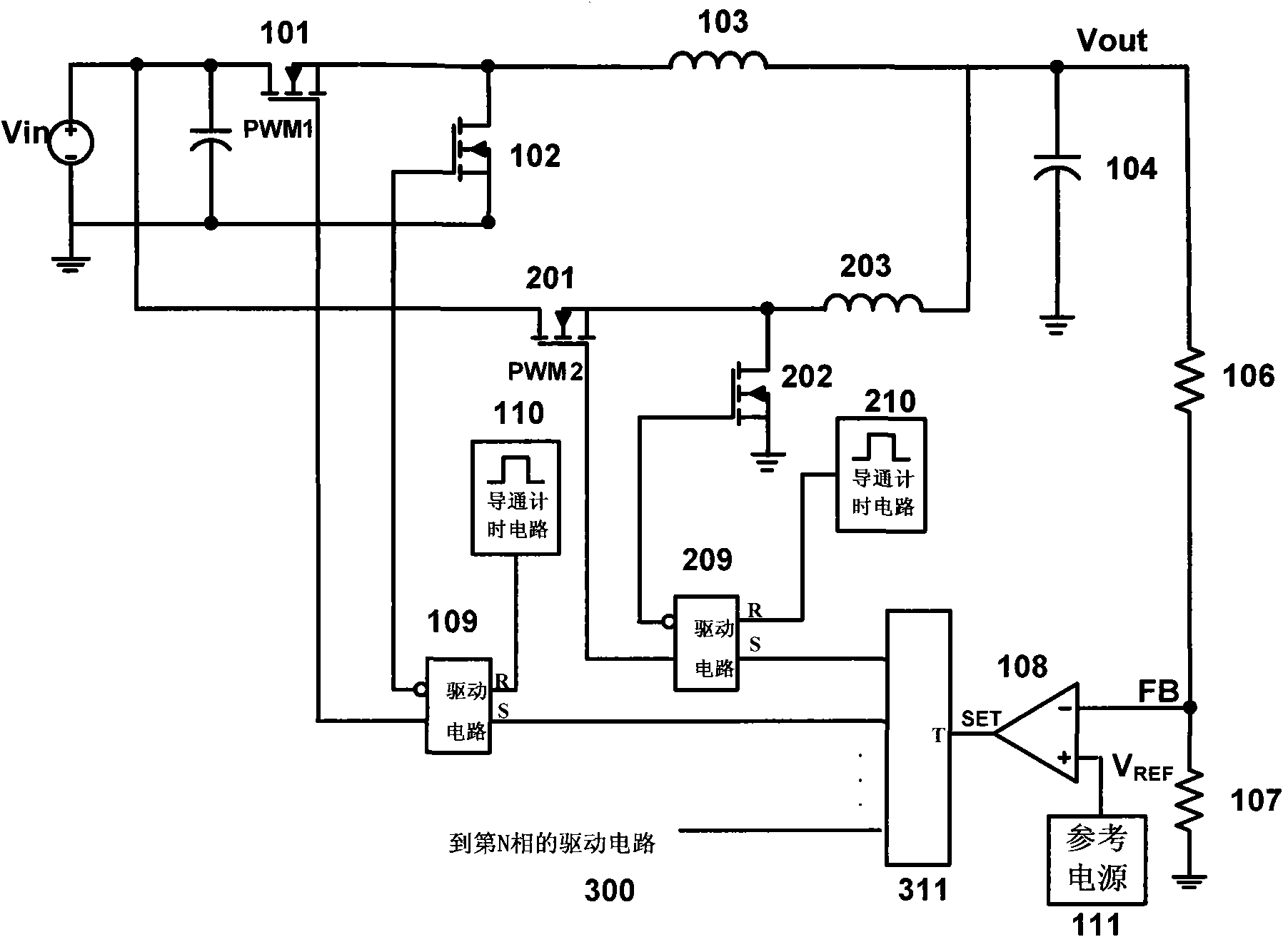
[0053] Figure 5A shows a schematic diagram of a two-phase COT converter 500 according to an embodiment of the present invention, wherein, with figure 2 The same components shown are denoted by the same reference numerals, and detailed descriptions thereof are omitted so as not to unnecessarily obscure the gist of the present invention.

[0054] and figure 2 In contrast, the two-phase COT converter according to the embodiment of the present invention also includes an on-time control circuit 212 for the second phase, which controls the second two-phase according to the on-time signals PWM1 and PWM2 of the first phase and the second phase The on-time timing circuit adjusts the on-time ...


PUM


Abstract

The invention provides an N-phase converter (N is an integer of more than or equal to 2), which comprises a switch for each phase, wherein the switch is controlled by a corresponding conducting signal. The converter is characterized by also comprising a control circuit which generates a control signal according to the conducting signal of each phase and is used for adjusting circuit parameters ofthe converter so as to uniformly distribute various phases. The invention also provides a method for the N-phase converter.

Description

technical field [0001] The present invention relates generally to power supplies, and more particularly to phase control for multiphase converters. Background technique [0002] Most electronic products, such as notebook computers, desktop computers, PDAs, etc., require a direct current (DC) power supply to provide regulated power to each functional module. The DC-DC synchronous step-down converter has the advantages of high efficiency and small size, and has been widely used. Low voltage ripple is the most basic requirement of a DC-DC synchronous buck converter. [0003] In order to obtain low voltage ripple, a constant on-time COT converter can be used as the control circuit of the DC-DC synchronous step-down converter. figure 1 shows the circuit schematic diagram of the single-phase COT converter 100, the output voltage V out The voltage sampling circuit composed of resistors 106, 107 feeds back the voltage sampling signal FB to the input terminal of the comparator 108...

Claims


Application Information

Patent Timeline
Patent Type & Authority Applications(China)
IPC IPC(8): H02M3/157H02M3/158
CPCH02M2003/1586H02M3/1584H02M3/1586
Inventor 任远程杨先庆欧阳茜李晓明
Owner CHENGDU MONOLITHIC POWER SYST
Why Eureka
Try Eureka