High-pressure liquid supplying displayable distributor

A distributor and liquid supply technology, applied in liquid distribution, gas/liquid distribution and storage, distribution devices, etc., can solve the problems of adjusting the amount of lubricating fluid in parts that cannot be lubricated, and adjusting separately

Inactive Publication Date: 2013-04-17
赵培龙
View PDF1 Cites 0 Cited by
  • Summary
  • Abstract
  • Description
  • Claims
  • Application Information

AI Technical Summary

Problems solved by technology

[0006] In order to solve the problem in the existing equipment that the amount of lubricating fluid in each lubricating part cannot be independently adjusted, the present invention provides a high-pressure liquid supply distributor with a display device. By using the liquid supply distributor, it is convenient to The lubricating fluid flow is individually adjusted for each outlet hole

Method used


Image

  • High-pressure liquid supplying displayable distributor
  • High-pressure liquid supplying displayable distributor
  • High-pressure liquid supplying displayable distributor

Examples


Embodiment Construction

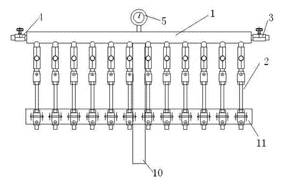
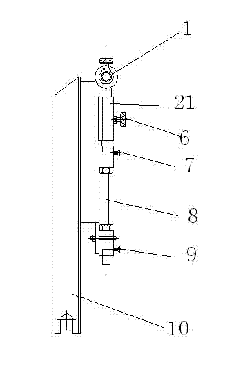
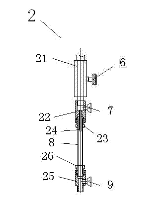
[0020] Such as figure 1 , 2 , 3, the high-pressure liquid supply disclosed in the present invention can display the distributor, including: main liquid pipe 1, several liquid pipes 2, liquid inlet valve 3, overflow valve 4, pressure gauge 5, control valve 6 and Fixed bracket. One end of the main liquid pipe 1 is provided with a liquid inlet valve 3 for connecting with a high-pressure liquid pump. The other end is provided with an overflow valve 4, and the overflow valve 4 is used for pressure relief when the pressure in the main liquid pipe 1 is too high. A number of dispensing pipes 2 are uniformly distributed along the axis of the main liquid pipe 1, and are in liquid communication with the main liquid pipe. Each dispensing pipe 2 is provided with a regulating valve 6 for regulating the flow of the main liquid pipe 1. The amount of liquid into each liquid pipe 2; the fixed bracket is used to support the main liquid pipe 1 and the fixed liquid pipe 2. Such as figure 2 A...


PUM


Abstract

The invention discloses a high-pressure liquid supplying displayable distributor. The distributor comprises a main liquid pipe, a plurality of liquid distribution pipes, a control valve and a fixing support; the main liquid pipe is connected with an external liquid supplying system; the plurality of the liquid distribution pipes are uniformly distributed along the axial direction of the main liquid pipe and are communicated with the main liquid pipe; each liquid distribution pipe is provided with an adjustment valve which is used for independently adjusting the volume of the liquid flowing from the main liquid pipe to each liquid distribution pipe; each liquid distribution pipe is also provided with a transparent section which is used for observing the liquid flow of the liquid distribution pipe; and the fixing support is used for supporting the main liquid pipe and fixing the liquid distribution pipes.

Description

technical field [0001] The invention relates to a high-pressure liquid supply distributor with a display device. Background technique [0002] In the applicant's earlier application number: 200710097510.5, titled: A high-efficiency energy-saving single-stage vacuum tile extruder, a vacuum tile extruder is recorded. Including the mud cylinder and machine head, the mud cylinder is provided with a material receiving box and a vacuum chamber, and a vacuum damping ring is provided near the input end of the vacuum chamber, and a spiral rib is arranged on the lining of the mud cylinder, and a Screw propulsion device, the output end of the mud cylinder is equipped with a machine head, and the extruding mud cylinder is provided with a tapered section whose inner diameter is connected with the machine head and gradually decreases along the direction of mud material travel, that is, the "machine neck"; the machine head is provided with A mud extrusion port corresponding to the section...

Claims


Application Information

Patent Timeline
Patent Type & Authority Patents(China)
IPC IPC(8): B67D1/00F17D1/14F17D3/01
Inventor 赵培龙
Owner 赵培龙
Why Eureka
Try Eureka