Non-rotating coupling device

A technology of coupling device and coupling end, applied in the direction of injection device, liquid injection device, coupling, etc., can solve the problem that the anti-rotation feature does not work.

Inactive Publication Date: 2011-09-28
戴维斯・A・怀特
View PDF5 Cites 11 Cited by
  • Summary
  • Abstract
  • Description
  • Claims
  • Application Information

AI Technical Summary

Problems solved by technology

That is, the male part of the current modified part is compatible with

Method used


Image

  • Non-rotating coupling device
  • Non-rotating coupling device
  • Non-rotating coupling device

Examples


Embodiment Construction

[0020] Those of ordinary skill in the art should understand that this document only describes exemplary embodiments and is not intended to limit the broader aspects of the present invention. The following exemplary embodiments are provided to further illustrate the present invention, and should not be construed as unduly limiting the scope of the present invention.

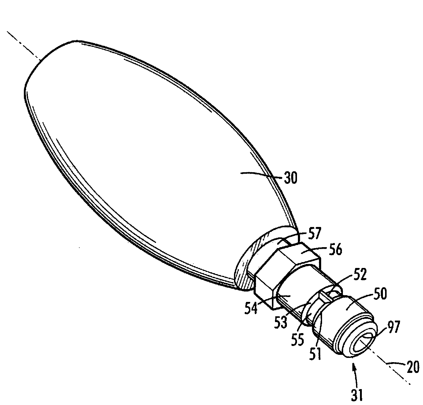
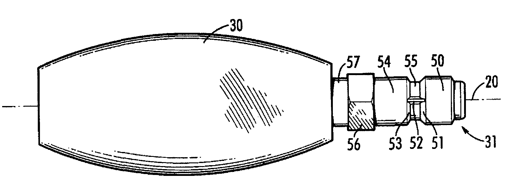
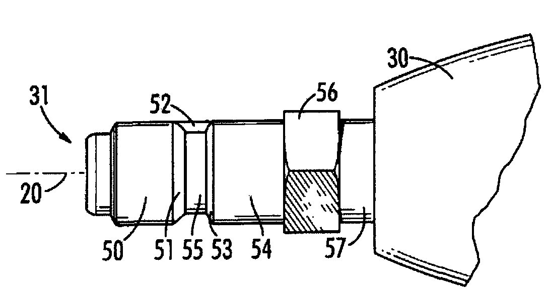
[0021] reference figure 2 , Figure 3A with Figure 3B , The non-rotating quick connector 10 includes: a male connector 31, a female connector 67, a tubular sleeve 62, a compression spring 63, a lock ring 60, an O-ring 61, and one or more locking balls or pins 64.

[0022] The male connector 31 includes an internal or external threaded portion 57 that forms an attachment end that is integrally connected to the male plug or coupling portion or end 50 by means of a shoulder portion 54 located in the middle of the length of the plug 31. The male plug 31 also includes: a fluid or air channel 97 that extends partially or c...


PUM


Abstract

The invention is a quick connect and disconnect coupling which limits the free rotation between the female socket and the male plug of the coupling with respect to one another. It comprises a male plug having a coupling end and a female socket having a coupling end with a receiving opening therein to receive the coupling end of the male plug when the connectors are in a coupled condition. A holding mechanism is associated with the coupled ends. The male plug includes a non-circular surface that interengages the locking balls within the female quick connect socket to substantially prevent relative rotation of the male plug in relation to the female socket. The coupling is particularly useful for attaching accessories as used in highly pressurized spray applications to allow the ability to rotationally adjust the dispensing action.

Description

Technical field [0001] The invention belongs to the field of quick connection connectors. Background technique [0002] Quick connect couplings are well known and are commonly used to connect aerodynamic tools to high pressure spray systems. The quick connect coupling allows the user to connect fluid or gas lines by simply pushing the two parts of the coupling together. There are many types of quick connect couplers in the field. These couplings are usually designed to rotate freely about a central axis. The problem with this type of coupling is that there are applications where little or no rotation is desired. In some dispensers, there are accessories such as the following: the user is required to rotate the nozzle to adjust the spray mode. This kind of accessory cannot be conveniently used in the quick connection structure for the following reasons: the conventional structure of the coupler will rotate freely, which cannot provide the resistance required to adjust the acce...

Claims


Application Information

Patent Timeline
IPC IPC(8): F16L37/24F16L37/26B05B7/24A62C35/68
CPCF16L37/23
Inventor 戴维斯・A・怀特
Owner 戴维斯・A・怀特
Why Eureka
Try Eureka