Air intake/evacuation valve for electric cooking appliance

A technology of intake and exhaust valves and electric cooking utensils, which can be used in household utensils, kitchen utensils, and cooking utensil lids, etc., and can solve problems such as difficulty in closing lids

Inactive Publication Date: 2011-10-05
DEA GENERAL AVIATION HLDG CO LTD
View PDF6 Cites 16 Cited by
  • Summary
  • Abstract
  • Description
  • Claims
  • Application Information

AI Technical Summary

Problems solved by technology

For this reason, the float valve mainly acts according to the pressure in the pot, so when there is a certain amount of steam and its steam p...

Method used


Image

  • Air intake/evacuation valve for electric cooking appliance
  • Air intake/evacuation valve for electric cooking appliance
  • Air intake/evacuation valve for electric cooking appliance

Examples


Embodiment 1

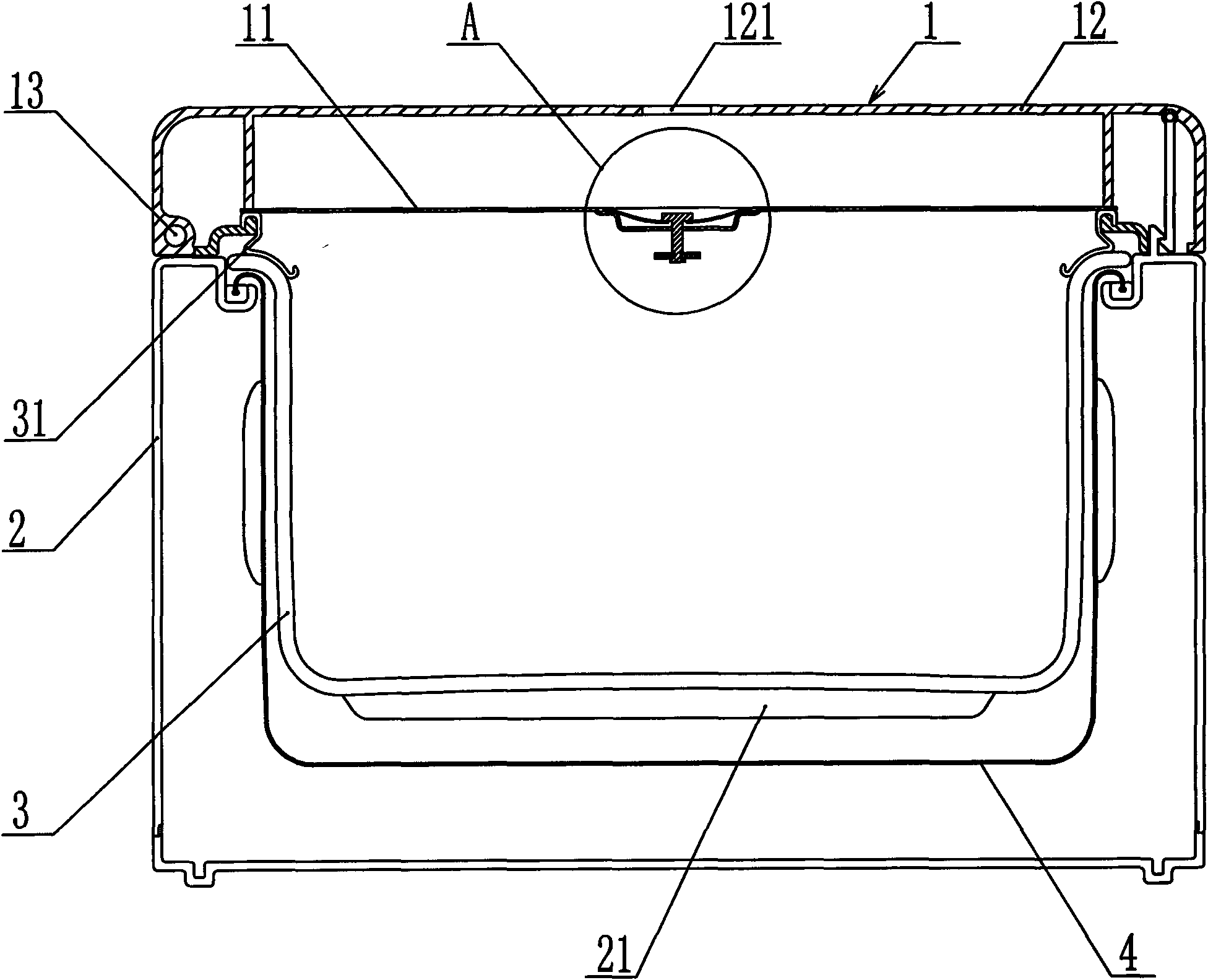
[0026] Such as figure 1 , figure 2 and image 3 Shown, a kind of electric cooker, comprises pot lid 1, pot body 2, inner pot 3 and heater 21, and wherein said pot body 2 is the main carrying part of described electric cooker, and inner pot 3, heater are arranged in it 21. The outer pot 4 and the electric control system of the electric cooker, the pot cover 1 is located on the upper part of the pot body 2 and an inner pot sealing ring 31 is arranged between the inner pot 3 and the outer pot 4 .

[0027] The pot cover 1 includes an outer shell 12 and an inner cover 11 , and the pot cover 1 is hingedly connected by a hinge device 13 provided between the outer shell 12 and the pot body 2 so that it can be flipped. The inner pot 3 is arranged in the pot body 2, and a heater 21 is arranged on the periphery of the inner pot 3, and the heater 21 is electrically connected with the control system of the micro-pressure cooker.

[0028] A pit 16 is set on the inner cover 11 , and an a...

Embodiment 2

[0035] Such as Figure 4 As shown, the difference from the first embodiment is that the valve core 5 is an inverted T-shaped soft plug 7 made of silicone rubber. The cushion block 8 is fixedly connected under the inner cover 11 . The upper part of the soft plug 7 protrudes into the air intake hole 14 , and the outer diameter of the upper part of the soft plug 7 is smaller than the inner diameter of the air intake hole 14 . In this way, when the temperature in the pot exceeds a certain value and the bimetal 6 also senses the corresponding temperature, the bimetal 6 deforms and pushes the soft plug 7 to move upward, and the protruding edge at the bottom of the soft plug 7 is closed The intake and exhaust holes 14 enable the pressure in the inner pot 3 to start to accumulate. When cooking finishes or uncovers pot cover 1 in the process of cooking, because pot cover 1 itself is in the air, described bimetal sheet 6 is cooled rapidly so that it resets to Figure 4 In the state s...

Embodiment 3

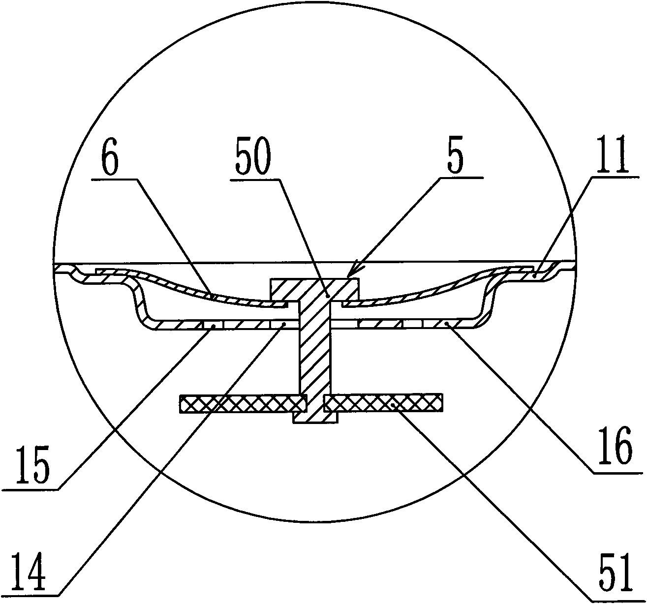
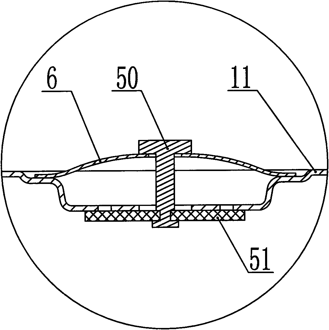
[0037] Such as Figure 5 As shown, it is a structural schematic diagram of the third embodiment applying the technical solution of the present invention. The difference from the first embodiment is that a housing 9 is provided on the inner cover 11 , and the housing 9 is set in the hole of the inner cover 11 by thread or embedding. An isolation platform 17 is arranged inside the housing, and the center of the isolation platform 17 is provided with the intake and exhaust holes 14 and the auxiliary intake and exhaust holes 15, and the bimetal 6 is erected on the isolation platform 17 And the middle part thereof is connected to the upper part of the "T" shaped rod part 50 of the valve core 5, and the lower part of the rod part 50 is provided with a sealing member 51. The inner diameter of the inlet and outlet holes 14 is larger than the outer diameter of the shaft portion 50 so that there is a gap therebetween. When the bimetal 6 is heated and deformed, it can drag the sealing ...


PUM


Abstract

The invention relates to an air intake/evacuation valve for an electric cooking appliance. The electric cooking appliance comprises a pot cover, wherein the pot cover is provided with air inlet/outlet holes; and the invention is characterized in that the air intake/evacuation valve comprises a valve core and a bimetallic strip connected with the valve core, wherein the bimetallic strip is arranged on the pot cover and drives the valve core to close or open the air inlet/outlet holes. The two ends of the bimetallic strip cross the air inlet/outlet holes and are arranged at one side of the pot cover, and the valve core is connected with the middle part of the bimetallic strip and is corresponding to the air inlet/outlet holes. The air intake/evacuation valve provided by the invention has the characteristics and advantages and can be applied to kitchenware such as a common electric cooker, a micropressure pot, a soup making pot, a simmering pot, a pressure cooker and the like.

Description

technical field [0001] The invention relates to an electric cooker, in particular to an intake and exhaust valve structure of the electric cooker. Background technique [0002] In a traditional ordinary electric rice cooker, the lid is provided with a vent hole that leads directly to the outside air. There is basically no pressure in the pot, and the boiling water vapor in the pot is directly discharged from the vent hole, which will take away a lot of heat. The energy consumption of this traditional electric cooker is very high; secondly in order to maintain the heat required for boiling water in the pot, the power and volume of the heater must be appropriately enlarged. [0003] For the micro-pressure cooker, the basic principle is to keep the water temperature in the pot close to the boiling point but rarely exceeds the boiling point. Among the existing technical solutions, the more typical technical solutions, whether it is the Chinese patent application number 200820005...

Claims


Application Information

Patent Timeline
IPC IPC(8): A47J27/08A47J27/00A47J36/06A47J36/38
Inventor 简伟文邹邦明李孜宇韦兴龙
Owner DEA GENERAL AVIATION HLDG CO LTD
Why Eureka
Try Eureka