3D dynamic display method

A dynamic display and 3D technology, applied in the direction of static indicators, instruments, electrical components, etc., can solve the problems that are not suitable for the use of household electrical appliances, and achieve the effect of satisfying richness, simple structure, and realizing industrialization

Inactive Publication Date: 2011-10-12
CHANGHONG MEILING CO LTD
View PDF0 Cites 0 Cited by
  • Summary
  • Abstract
  • Description
  • Claims
  • Application Information

AI Technical Summary

Problems solved by technology

This kind of 3D image is only suitable for some specific occasions such as cine

Method used


Image

  • 3D dynamic display method
  • 3D dynamic display method
  • 3D dynamic display method

Examples


Embodiment

[0014] Example: see Figure 1-3 , the 3D dynamic display method described in the present embodiment, comprises the following steps:

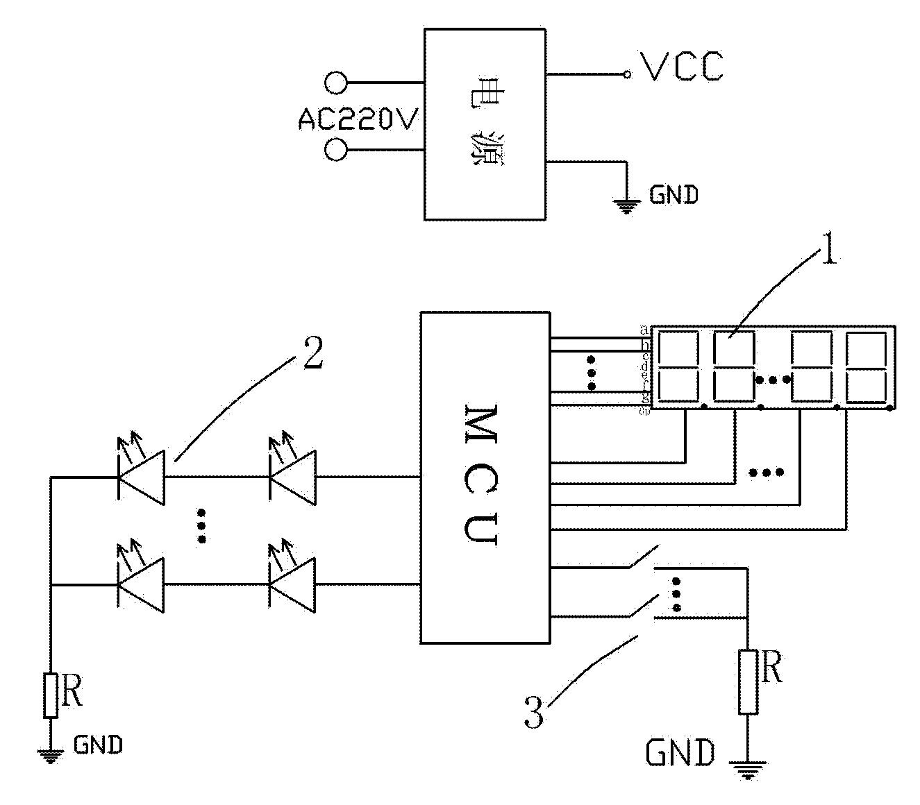
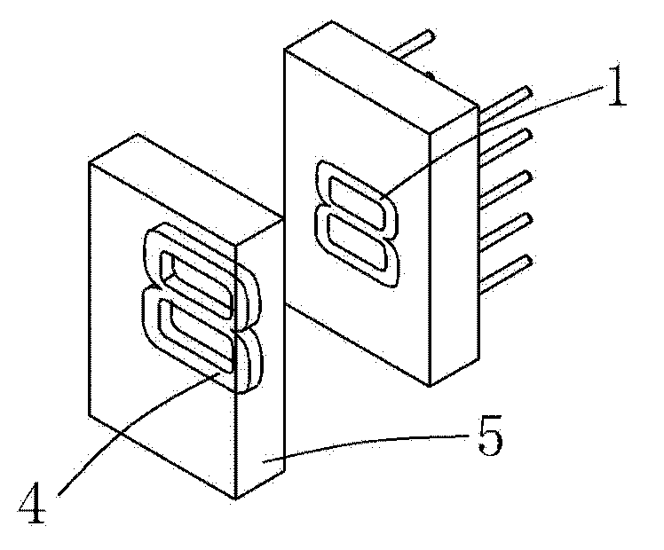
[0015] A. Set the backlight source. The backlight source includes a power supply, MCU, digital tube 1, diode 2 and control key 3. The digital tube 1 and diode 2 are connected to the output terminal of the MCU. The control key 3 controls the output frequency of the MCU to realize the transformation of the LED light. , the LED lamp is used as the backlight of the substrate 5 .

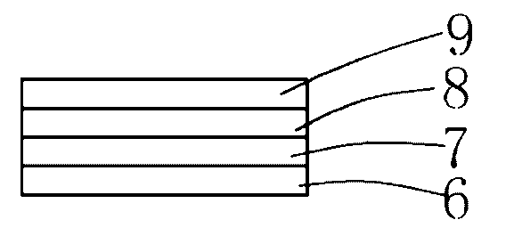
[0016] B, 3D label is set, and described 3D label comprises adhesive layer 6, information recording layer 7, optical layer 8 and surface protective layer 9, and described adhesive layer is pasted on described nixie tube, and described information recording layer records pattern 4 information.

[0017] Control the light-emitting diode or digital display tube through the MCU output signal, and adjust the output frequency of PWM to realize the visual illusion and achieve th...


PUM


Abstract

The invention discloses a 3D dynamic display method. The 3D dynamic display method comprises the following steps of: A, setting a backlight light source comprising a power supply, an MCU (micro control unit), a nixie tube, a diode and a control key, wherein the nixie tube and the diode are connected with an output end of the MCU, and the control key controls the output frequency of the MCU to implement conversion of LED (light-emitting diode) lamps of the nixie tube; B, setting a 3D label comprising an adhesive layer, an information recording layer, an optical layer and a surface protection layer, wherein the adhesive layer is adhered to the nixie tube, and the information recording layer records pattern information. In the invention, the change of 3D effect is realized through the change of the backlight light source.

Description

Technical field: [0001] The invention relates to a 3D dynamic display method, belonging to the technical field of 3D dynamic display. Background technique: [0002] With the rapid development of today's social economy, it is worth thinking about how to bring consumers a happy and high-quality electrical product, so that it can bring consumers a real, interesting and humanized new experience. In other various industries, 3D stereoscopic display technology is becoming more and more popular, it brings a brand-new three-dimensional effect to consumers, and makes people feel immersive. There are two kinds of 3D stereoscopic display technologies on the market, those with glasses and those without glasses, but they are all realized by the principle that human eyes observe objects with slightly different angles, can distinguish objects from near and far, and produce stereoscopic vision. The 3D effect display layer is to use this feature to displace and display the picture details o...

Claims


Application Information

Patent Timeline
IPC IPC(8): G09G3/14H04N13/00
Inventor 白连社吴园林万禄季涛
Owner CHANGHONG MEILING CO LTD
Why Eureka
Try Eureka