Electronic camera

A camera and electronic technology, applied in TV, electrical components, color TV, etc., can solve the problem of multiple motion vectors judging the attributes of the shooting field of view, and achieve the effect of improving camera performance

Inactive Publication Date: 2011-10-12
SANYO ELECTRIC CO LTD
View PDF6 Cites 3 Cited by
  • Summary
  • Abstract
  • Description
  • Claims
  • Application Information

AI Technical Summary

Problems solved by technology

[0004] However, in the background art, the attribute of the imaging field of view is not determined based on a plurality of motion vectors detected corresponding to a plurality of positions of the imaging surface, and the adjustment standard of the imaging condition is not set according to the determined attribute. set as different
Therefore, there are limitations in the camera performance in the background technology

Method used


Image

  • Electronic camera
  • Electronic camera
  • Electronic camera

Examples


Embodiment approach

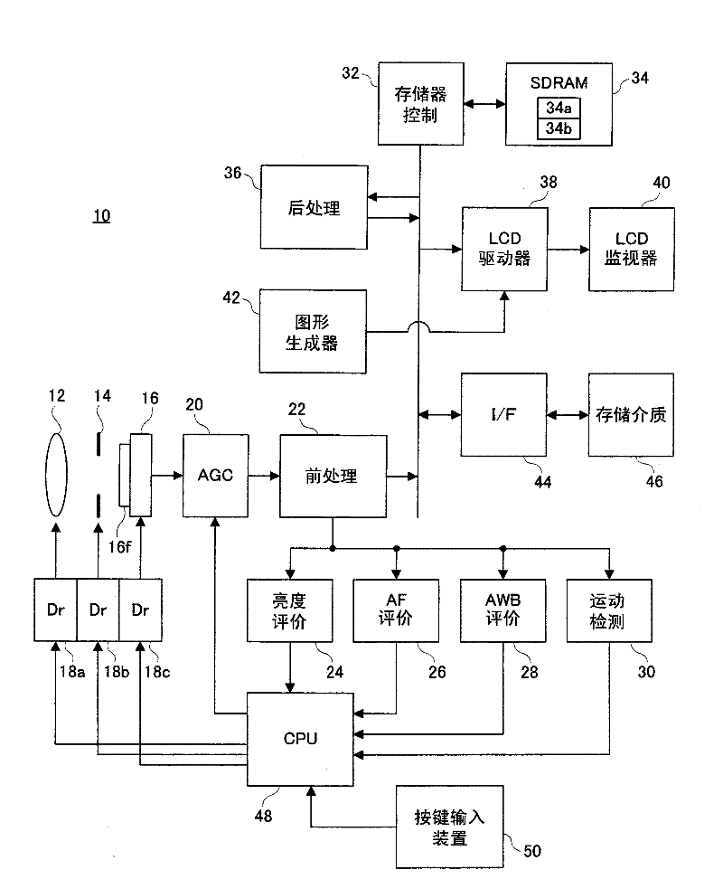
[0058] refer to figure 2 , The digital video camera 10 of this embodiment includes a focus lens 12 and an aperture unit 14 driven by drivers 18a and 18b, respectively. The optical image of the captured field of view is irradiated onto the imaging surface of the image sensor 16 through these components.

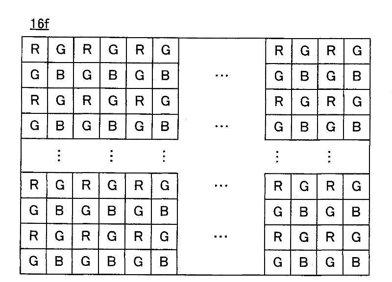
[0059] A plurality of light-receiving elements (=pixels) are arranged two-dimensionally on the imaging plane, and the imaging plane consists of image 3 A primary color bayer array is shown overlaid by color filters 16f. Specifically, the color filter 16f corresponds to an R (Red, red) filter element, a G (Green, green) filter element, and a B (Blue, blue) filter element arranged in a mosaic pattern. shape filter. The light receiving elements arranged on the imaging surface correspond to the filter elements constituting the color filter 16f on a one-to-one basis, and the amount of charge generated by each light receiving element reflects the intensity of light correspondin...


PUM


Abstract

The invention provides an electronic camera. An image sensor 16 has the functions of capturing the pick-up face of the scene and repeatedly outputting the scene images. A CPU 48 adjusts the pick-up condition along any one one of a plurality of program graphs including a specific program graph suitable for a dynamic scene. The CPU 48 determines whether the movement of the pick-up scene image based on the originally image data satisfies a first condition according to the movement vector output from a movement detecting circuit 30 and a luminance of the pick-up scene image based on the originally image data satisfies a second condition according to a luminance evaluating value outputted from a luminance evaluating circuit 24; and the CPU permits the referring of the specific program graph when the determining result is satisfied and restricts or forbids the referring of the spefic program graph when at least one of the determining result is not satisfied. Accordingly, the pick-up performance is improved.

Description

technical field [0001] The present invention relates to an electronic camera, and more particularly, to an electronic camera that adjusts imaging conditions with reference to movement of a captured field image output from an imaging device. Background technique [0002] An example of such a camera is disclosed in Patent Document 1. According to this background art, a plurality of motion vectors respectively corresponding to a plurality of positions on an imaging surface are detected based on image data output from an imaging unit. The motion of the camera is determined by performing a majority voting operation on a plurality of detected motion vectors. Image data output from the imaging unit is also stored in the image storage unit. When the motion of the camera determined by the majority voting operation corresponds to hand shake, the position of a part of image data to be read from the image storage unit for display is adjusted so as to correct the hand shake. [0003] ...

Claims


Application Information

Patent Timeline
Patent Type & Authority Applications(China)
IPC IPC(8): H04N5/232
CPCH04N23/6811H04N23/683H04N23/72H04N23/71
Inventor 藤原健山本诚司
Owner SANYO ELECTRIC CO LTD
Why Eureka
Try Eureka