Simple-structure sizing die for optical cable or power cable

A technology for sizing molds and cables, which is applied in the field of cables, can solve the problems of long time for mold replacement, inconvenient use, waste of resources, etc., and achieve the effects of saving personnel and time costs, avoiding wrong mold selection, and improving production efficiency

Inactive Publication Date: 2019-10-08
CHANGSHU GREATER MECHANICAL PROD DESIGN CO LTD
View PDF0 Cites 4 Cited by
  • Summary
  • Abstract
  • Description
  • Claims
  • Application Information

AI Technical Summary

Problems solved by technology

[0002] With the continuous development of my country's communication industry, there are many types of optical cables or cables, and the cable diameters and sizes are mixed. There are also many molds of different sizes that need to be configured, and some molds are only used once or rarely. The order leads to idleness, high cost and waste of resources; production personnel often choose the wrong mold, which brings greater challenges to mold management; at the same time, when there is no mold with the optimal size in the mold library, it is necessary to re-customize Mold, or choose a mold that is close but relatively large in size, so that there is a large gap between the inner wall of the sheath of the formed optical cable or cable and the cable core, and more filling materials are needed to fill the gap, and the outer diameter of the optical cable is also larger. Relatively large, more sheath materials are used; when reeling, less optical cables or cables are loaded on the same size reel, and the transportation cost is higher; the current cable mold is still complicated in structure, inconvenient to use, and takes a long time to replace the mold problems, and when the order is miscellaneous, the mold is replaced frequently, which also makes the production efficiency of optical cable or cable not high

Method used


Image

  • Simple-structure sizing die for optical cable or power cable
  • Simple-structure sizing die for optical cable or power cable
  • Simple-structure sizing die for optical cable or power cable

Examples


Embodiment 1

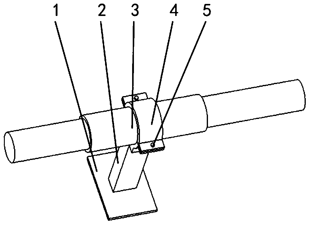
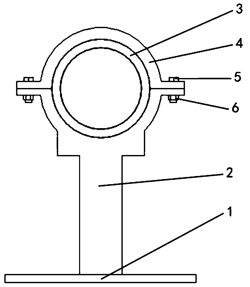
[0027] please see figure 1 , Figure 8 , Figure 9 with Figure 10 , a sizing mold with a simple structure for optical cables or cables, has a base 1, a support unit 2, a mold body 3 and a fixing member 4, and is characterized in that the support unit 2 is composed of a support unit body 22, and the upper end of the support unit body 22 is formed The support unit notch 21 forms a plurality of first fixing holes 23 on the left and right sides, the mold main body 3 is located in the support unit notch 21, and the support unit 2 is also provided with a fixing member 4, and the fixing member 4 is formed by the fixing member main body 41 Composition, below the main body 41 of the fixing member is also provided with a fixing member notch 42, and a plurality of second fixing holes 43 are formed on the left and right sides, and the bolt 5 passes through the first fixing hole 23, the corresponding second fixing hole 43 and connects with the nut. 6, the fixing member 4 and the suppor...

Embodiment 2

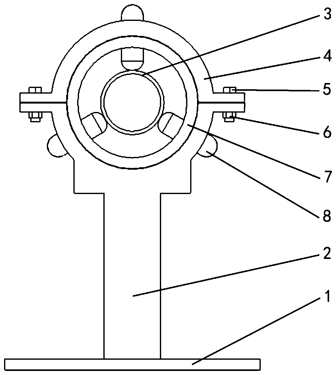
[0029] please see image 3 , Figure 5 , Image 6 , Figure 8 , Figure 9 with Figure 10 , a simple structure sizing mold for optical cable or cable, has a base 1, a support unit 2, a mold body 3, a fixing member 4, a rotating rod 8 and a positioning frame 7; it is characterized in that the support unit 2 consists of a support unit body 22 The upper end of the support unit main body 22 forms a support unit notch 21, a plurality of first fixing holes 23 are formed on the left and right sides, the positioning frame 7 is located in the support unit notch 21, the mold main body 3 is located in the positioning frame 7, and the positioning frame 7 is made of locating frame main body 71, and positioning chamber 73 is formed in the middle, and three threaded holes 72 are formed in the same plane of locating frame main body 71, and each threaded hole 72 has a rotating rod 8 respectively, and described rotating rod is formed by rotating rod The main body 81, the thread 82 position...

Embodiment 3

[0031] please see Figure 4 , Figure 5 , Figure 7 , Figure 8 , Figure 9 with Figure 10, a simple structure sizing mold for optical cable or cable, has a base 1, a support unit 2, a mold body 3, a fixing member 4, a rotating rod 8 and a positioning frame 7; it is characterized in that the support unit 2 consists of a support unit body 22 The upper end of the support unit main body 22 forms a support unit notch 21, a plurality of first fixing holes 23 are formed on the left and right sides, the positioning frame 7 is located in the support unit notch 21, the mold main body 3 is located in the positioning frame 7, and the mold main body 3 is curled, and one end of the mold main body 3 is in contact with the inner wall of the mold main body 3 but does not adhere to form the inner cavity of the mold main body 3. The positioning frame 7 is composed of a positioning frame main body 71, and a positioning cavity 73 is formed in the middle. The body is also provided with a mol...


PUM


Abstract

The invention belongs to the field of cables, and particularly relates to a simple-structure sizing die for an optical cable or a power cable. The simple-structure sizing die is provided with a base,a supporting unit, a die main body and a fixing member. The simple-structure sizing die is characterized in that the supporting unit is formed by a supporting unit main body, a supporting unit concaveopening is formed in the upper end of the supporting unit main body, a plurality of first fixing holes are formed in the left and right sides, the die main body is located in the supporting unit concave opening, and the fixing member is further arranged above the supporting unit; and the fixing member is formed by a fixing member main body, a fixing member concave opening is formed below the fixing member main body, a plurality of second fixing holes are formed in the left and right sides, bolts are matched with nuts, and the supporting unit is located on the base. The simple-structure sizingdie solves the problem that the die needs to be frequently replaced according to the outer diameter of a cable core, spare dies are many, mistakes are prone to being made during selection and use, and the optimal die may not be selected. The simple-structure sizing die has the advantages that the size of the die main body can be steplessly adjusted, the cost is saved, the die does not need to befrequently changed, the structure is simple, and installation is convenient to achieve.

Description

technical field [0001] The invention belongs to the field of cables, in particular to a sizing die with a simple structure for optical cables or cables. Background technique [0002] With the continuous development of China's communication industry, there are many types of optical cables or cables, and the cable diameters and sizes are mixed. There are also many molds of different sizes that need to be configured, and some molds are only used once or rarely. The order leads to idleness, high cost and waste of resources; production personnel often choose the wrong mold, which brings greater challenges to mold management; at the same time, when there is no mold with the optimal size in the mold library, it is necessary to re-customize Mold, or choose a mold that is close but relatively large in size, so that there is a large gap between the inner wall of the sheath of the formed optical cable or cable and the cable core, and more filling materials are needed to fill the gap, a...

Claims


Application Information

Patent Timeline
Patent Type & Authority Applications(China)
IPC IPC(8): B29C33/12B29C33/38B29C33/30
CPCB29C33/123B29C33/305B29C33/308B29C33/38
Inventor 沈群华方亚琴
Owner CHANGSHU GREATER MECHANICAL PROD DESIGN CO LTD
Why Eureka
Try Eureka