Disk Selecting Device And Disk Device

a selection device and disk technology, applied in the direction of information storage, instruments, data recording, etc., can solve the problems of difficult to use one type of cam plate, large size of the entire device for installing the magazine, and large size of the magazine itself, so as to prevent an erroneous selection, and reduce the size of the devi

Inactive Publication Date: 2008-11-13
CLARION CO LTD
View PDF4 Cites 2 Cited by
  • Summary
  • Abstract
  • Description
  • Claims
  • Application Information

AI Technical Summary

Benefits of technology

[0015]In the present invention described above, the cylindrical drum cam rotates and thereby a disk holding section is selected, thus only a small space is necessary and the degree of freedom for disposing the members is high, compared to a cam plate or the like in which securing of a slide stroke and interference between other members need to be considered. Further, when the disk selecting cam selects a disk holding section, even when the disk selecting cam contacts with the disk holding section which is not the object of selection, the transmitting member permits the rotation of the drum cam, thus the disk selecting cam can be withdrawn from the disk holding section which is not the object of selection, whereby erroneous selection is prevented.
[0046]According to the present invention described above, the disk selecting device and the disk device, which require only a small space and can prevent an erroneous selection, can be provided.

Problems solved by technology

Therefore, the walls of the magazine main body are thick, and as a result the sizes of the magazine itself and the entire device for installing the magazine are large.
In addition, in order to take out a disk housed in the magazine and play the disk, it is necessary to provide a sufficient space in the device, thus the size of the device increases.
However, since it is difficult to use one type of cam plate to realize a plurality of functions such as positioning and splitting the trays as described above, a plurality of types of cam plates are disposed separately.
However, each of these cam plates needs to secure a required slide stroke, thus the size of a required space increases and the degree of freedom for disposing other members is limited in order to prevent an interference between the sliding cam plates.
Moreover, each of the flat cam plates has a large contact area contacting with other member, and has to be slid by relatively strong drive power, thus even if the position of the tray, which is the object of selection, and the position of the cam of the cam plate are misaligned due to vibration, the misaligned positions cannot be corrected in the middle of operation.
However, for example, in the case where excellent resistance to vibration is requested as in the on-board disk device, if a disk is held on the tray simply by means of the bias force of the biasing member only, the position of the holding member is changed when strong vibration or the like occurs, destabilizing the position of the disk.
Particularly, the device is made complex and large by providing and accordingly synchronizing a mechanism for selecting a tray on which a desired disk is held, a mechanism for displacing the holding member in order to release the disk when playing or inserting / ejecting the disk, and a mechanism for locking the holding member when housing the disk.

Method used


Image

  • Disk Selecting Device And Disk Device
  • Disk Selecting Device And Disk Device
  • Disk Selecting Device And Disk Device

Examples


Embodiment Construction

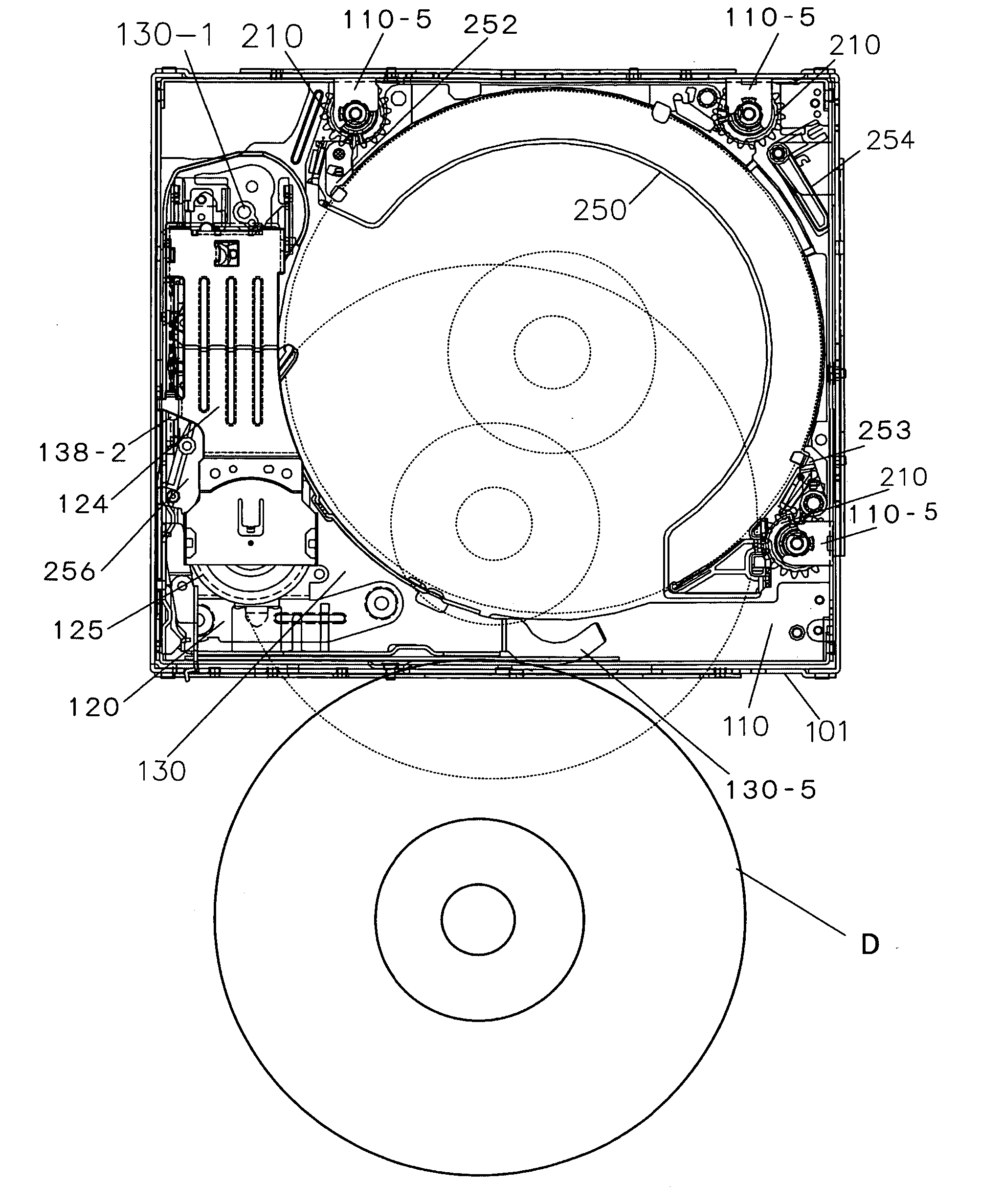
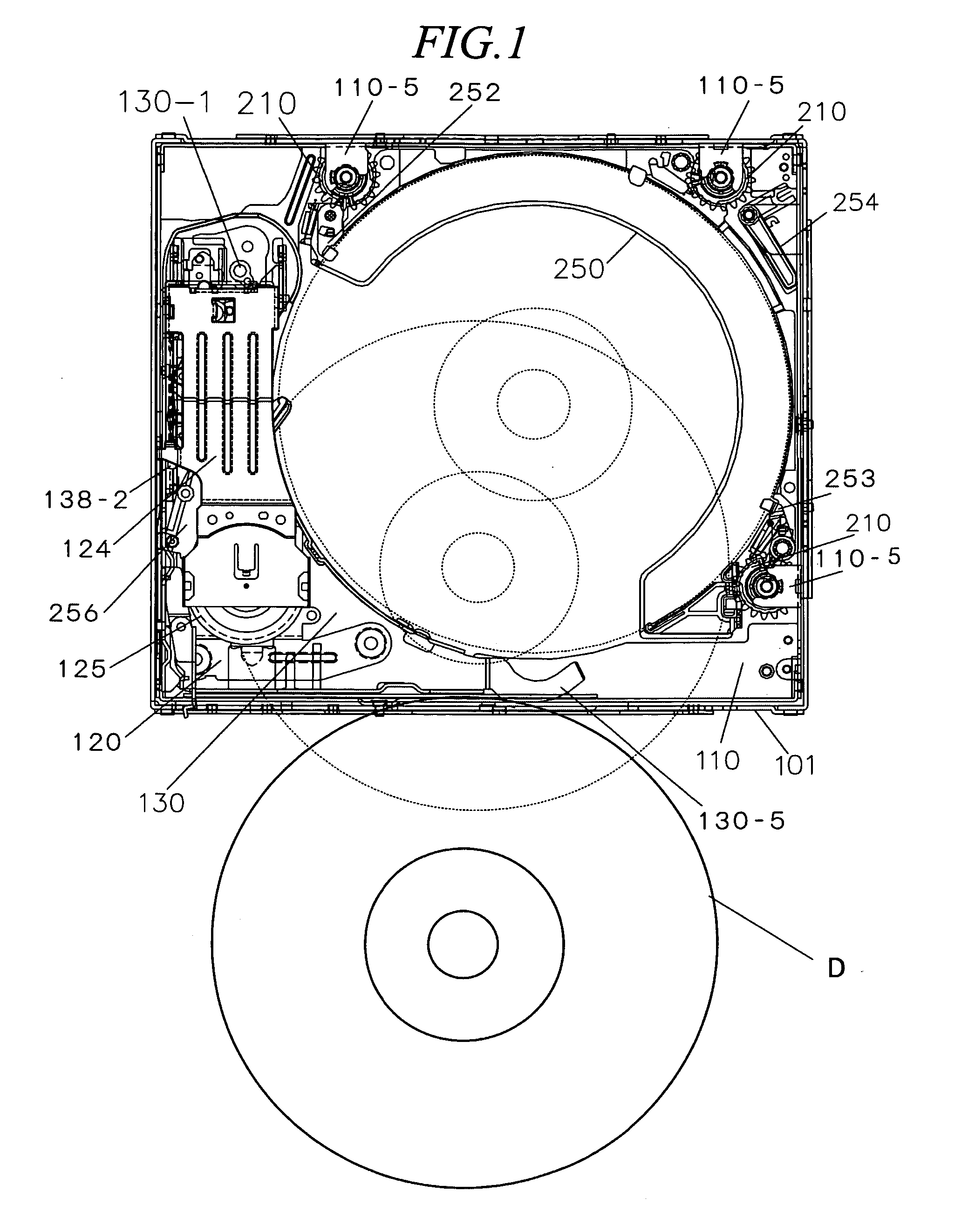
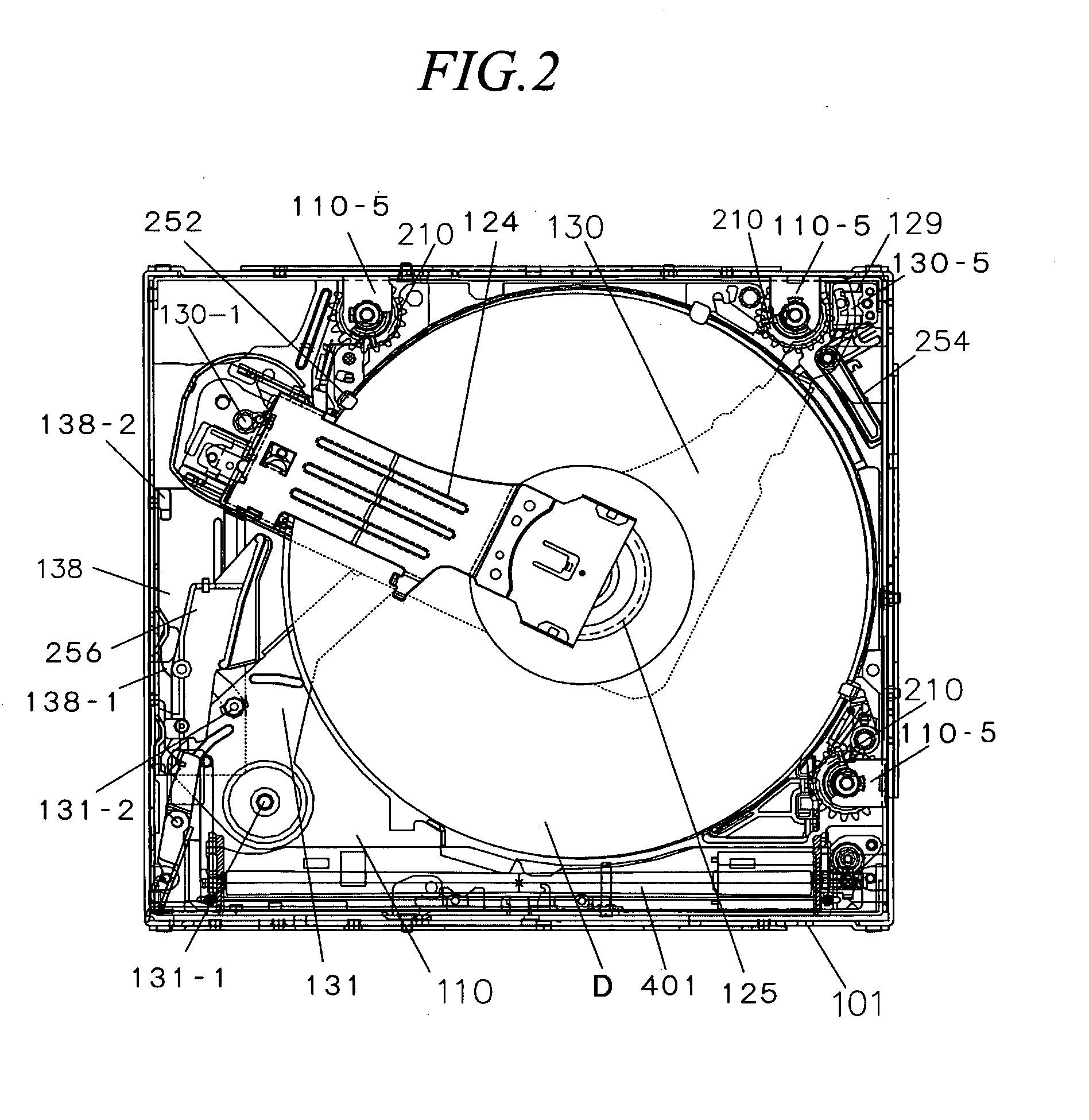
[0089]Hereinafter, an embodiment (“present embodiment”, hereinafter) of an on-board disk device to which the present invention is applied is described in detail with reference to the drawings. It should be noted that the disk holding sections correspond to the trays, the axis section corresponds to the drum gear, and the drive moving mechanism corresponds to the pick arm and a mechanism for rotating the pick arm, the disk holding sections, the axis section, and the drive moving mechanism being described in the claims. Furthermore, in the following descriptions of the drawings, the front face side of the disk device is the head side, the back face side of same is the rear side, and the vertical and longitudinal directions correspond to the directions viewed from the front face side of the disk device.

A. Entire Configuration

[0090]The present embodiment has the following schematic configurations as shown in FIG. 1 and FIG. 2:

[0091](1) Trays 250 capable of holding disks D separately.

[00...


PUM

PropertyMeasurementUnit
sizeaaaaaaaaaa
sizeaaaaaaaaaa
drive poweraaaaaaaaaa

Abstract

To provide a disk selecting device and disk device which require only a small space and can prevent an erroneous selection of disks.The disk selecting device comprises a plurality of trays 250 for holding a plurality of disks D respectively, and a mechanism for separating a tray 250, which is the object of selection, from other trays 250 comprises: a drum gear 211 which is provided in the vicinity of the trays 250 and rotated by a drive mechanism; a cylindrical drum cam 210 into which the drum gear 211 is inserted; a disk selecting cam groove 210-1 which is formed on a periphery of the drum cam 210 and leads the tray 250, which is the object of selection, in a direction of separating the tray 250 from other trays 250; and a drum sleeve 212 which is provided between the drum gear 211 and the drum cam 210, permits the rotation of the drum cam 210 so that the disk selecting cam groove 210-1 is withdrawn from the trays 250 which are not the object of selection, and transmits drive power from the drum gear 211 to the drum cam 210.

Description

TECHNICAL FIELD[0001]The present invention relates to a disk selecting device for selecting a desired disk from a plurality of disk holding sections, and particularly to the improvement of a disk selecting device and disk device which, when playing a disk, can move the disk holding sections to form a space for inserting a drive unit thereto to play the disk.BACKGROUND ART[0002]Conventionally, there has been widely used a disk device which is installed with a magazine for housing disks and in which a disk taken out from the magazine is automatically played. Such a disk device is excellent in operability since the disks do not have to be inserted or ejected one by one every time when playing the disk.[0003]However, it is required that the magazine attached or detached with respect to the device be strong enough to protect a plurality of disks held therein when taking out the magazine to the outside. Therefore, the walls of the magazine main body are thick, and as a result the sizes of...

Claims


Application Information

Patent Timeline
Patent Type & Authority Applications(United States)
IPC IPC(8): G11B17/04G11B17/26
CPCG11B17/056G11B17/26
Inventor HANDA, HIROTOTAKAHASHI, AKIRA
Owner CLARION CO LTD
Why Eureka
Try Eureka