
Electrical terminal module

A terminal module and electrical wiring technology, applied in the field of electrical wiring terminal modules, can solve problems such as application inability to achieve, and achieve the effects of avoiding unintentional damage, reducing the structure width, and avoiding additional abrasion and/or wear.

Active Publication Date: 2011-10-12
PHOENIX CONTACT GMBH & CO KG
View PDF6 Cites 1 Cited by
  • Summary
  • Abstract
  • Description
  • Claims
  • Application Information

AI Technical Summary

Problems solved by technology

Applications with elongated components with a height of less than 8 mm in the electrical terminal block are also not possible here

Method used


Image

  • Electrical terminal module
  • Electrical terminal module
  • Electrical terminal module

Examples


Embodiment Construction

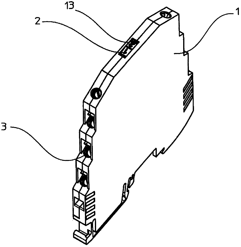
[0091] figure 1 A preferred embodiment of an electrical connection terminal module of the type of the invention is shown. The housing has a plurality of contact elements 3 to which electrical wires can be connected. The electrical wires form connections with sensors, actuators and / or other electrical wiring terminal modules. The fixing of the wire on the electrical connection terminal module is realized by a screw terminal, an elastic terminal or the like in a known technique.

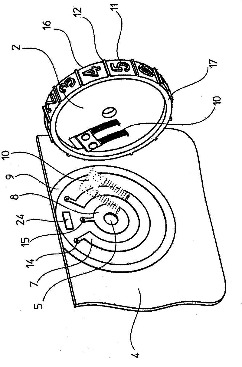
[0092] On the top side of the housing, there is an adjusting member 2, which can be used to adjust or change the function of the electrical connection terminal module. In this regard, a housing opening 13 is provided in the housing 1, through which the adjustment member 2 can be adjusted. Adjusting part 2 in figure 1 The middle is formed as an adjusting wheel and is directly arranged on the terminal board 4.

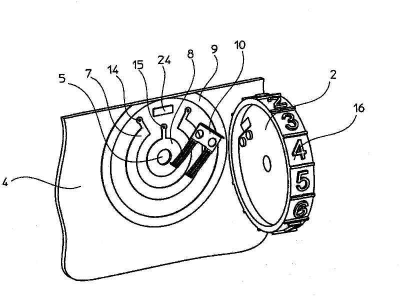
[0093] figure 2 It shows a schematic diagram of the adjusting member in a state where it has n...


PUM


Abstract

The invention relates to an electrical terminal module to which a large number of electrical conductors are connected and on which at least one predetermined function, in particular a timing function, can be executed. These functions can often be set, adjustable electrical components being arranged on a printed circuit board, which is arranged in the terminal module, for this reason. Since electrical terminal modules of this kind are required in ever narrower forms, it is necessary to create ways of being able to even arrange the adjustable electrical components in the housing too, but at the same time maintaining the ease with which the function can be set. The invention solves this problem by virtue of directly mounting the adjusting means on the printed circuit board which is installed in the housing.

Description

Technical field [0001] The present invention relates to an electrical wiring terminal module, which includes a plurality of electrical contact elements for connecting electrical wires, a housing for accommodating at least one wiring board, and an adjusting member for changing at least one electrical parameter of a circuit. The circuit is provided with electronic components for realizing the preset function, especially the timer function, wherein at least a part of the adjusting member can be operated through an opening on at least one side wall of the housing, and from outside Able to swing or rotate. Background technique [0002] The above-mentioned electrical wiring terminal modules are mainly assembled with other electronic and / or electrical wiring terminal modules in a switch cabinet. The fixing of the electrical connection terminal modules in the switch cabinet is usually realized by being fastened on the supporting frame, wherein these electrical connection terminal module...

Claims


Application Information

Patent Timeline
Patent Type & Authority Applications(China)
IPC IPC(8): H01H19/00H01H19/02H01H19/03H01H19/58G04C23/10
CPCG04C23/46H01H19/001H01H19/025H01H19/03H01H19/585H03J1/06
Inventor 弗兰克·哈克梅耶尔克里斯蒂安·施塔克于尔根·克莱因施密特
Owner PHOENIX CONTACT GMBH & CO KG
Learn More