Nail puller

A technology for nail pullers and nail parts, applied in the direction of nail pullers, manufacturing tools, etc., can solve the problems of fulcrum changes, unfavorable pull out of long nail needles, etc., and achieve the effect of wide applicability

Inactive Publication Date: 2011-10-19
APEX MFG
View PDF9 Cites 8 Cited by
  • Summary
  • Abstract
  • Description
  • Claims
  • Application Information

AI Technical Summary

Problems solved by technology

[0003] The fulcrum of existing nail pullers is generally fixed and cannot change with the change of the handle's depression stroke; this design often has a lack of long nails that are not conducive to pulling out

Method used


Image

  • Nail puller
  • Nail puller
  • Nail puller

Examples


Embodiment Construction

[0053] The structural features, usage methods and expected effects of the present invention will be described below through several preferred embodiments, but they are not intended to limit the protection scope of the claims of the present invention, and are described in advance.

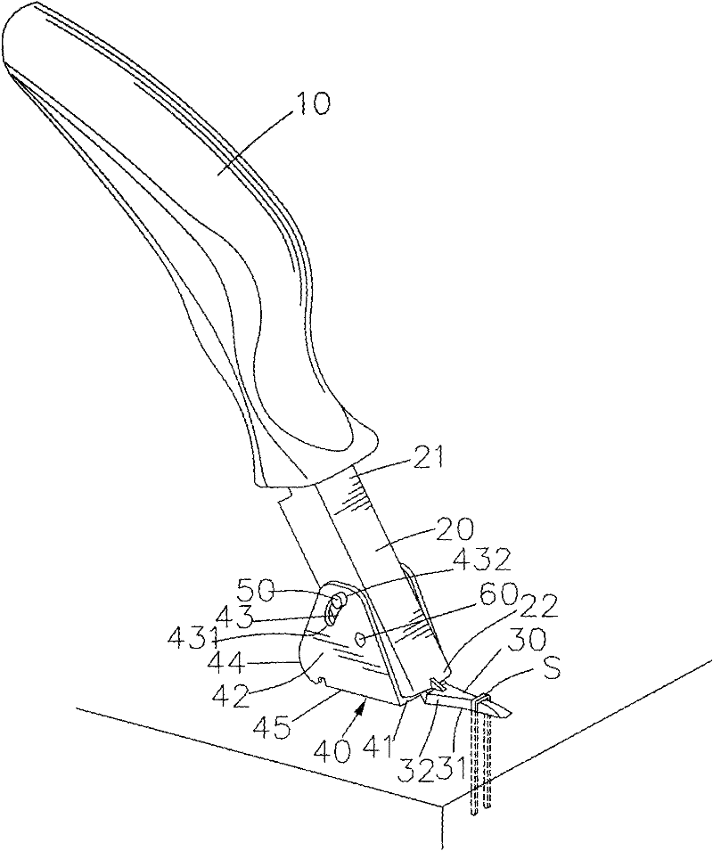
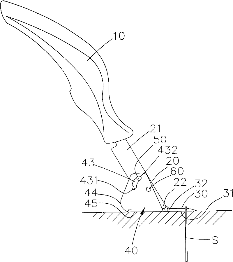
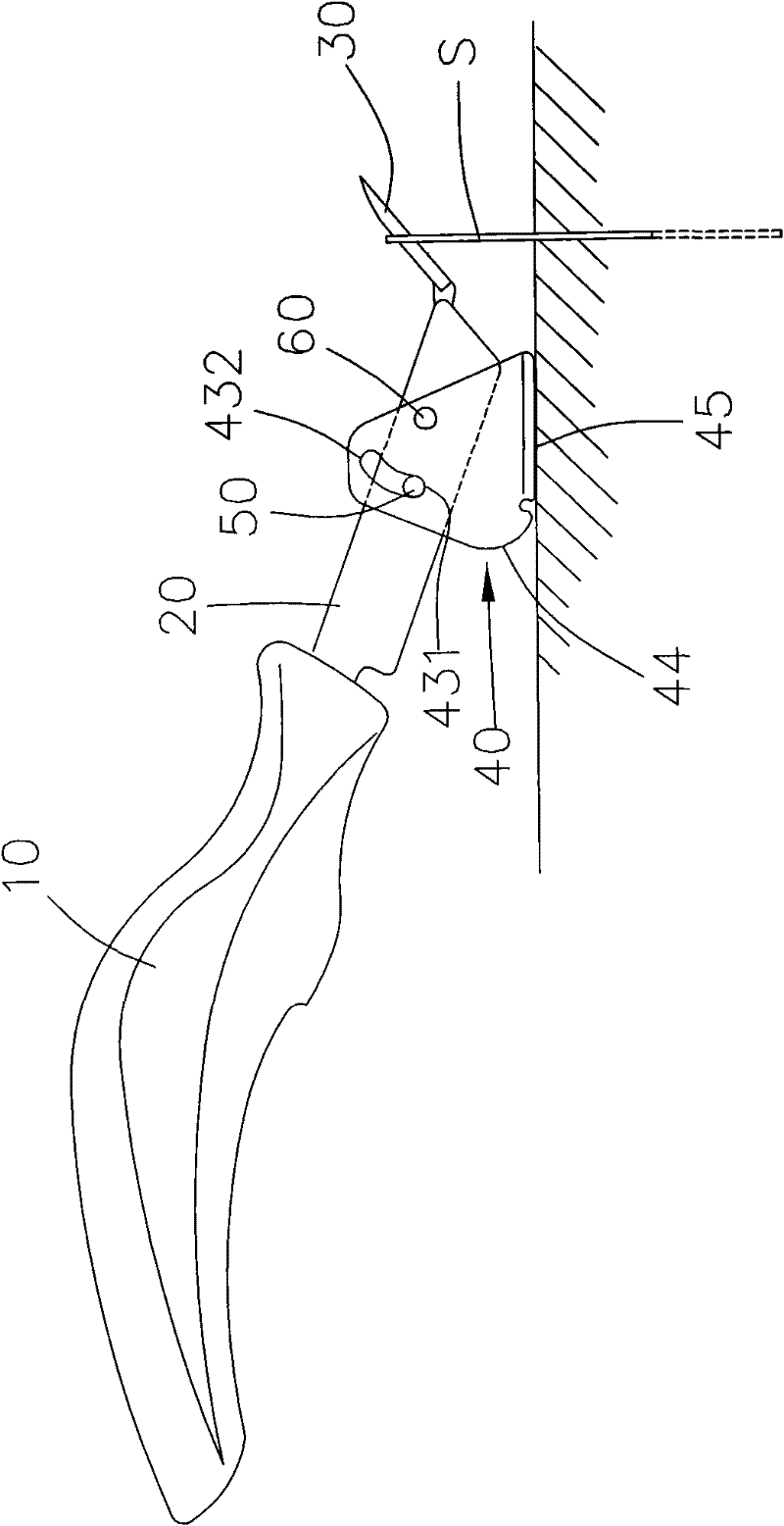
[0054] First, please refer to figure 1 . In the first embodiment of the present invention, the nail puller includes a handle 10 , a coupling section 20 , a nail puller 30 , a swing base 40 and a pair of positioning pins 50 .

[0055] The handle 10 is for the user to hold, and when the nail puller is working, the user applies force to press down, so as to pull a nail S. The combined section 20 extends forward from one end of the handle 10, the combined section 20 has a first end 21 and a second end 22, the first end 21 of the combined section 20 is connected to the handle 10, and the handle There may also be an appropriate included angle between the handle 10 and the joint section 20 .

[0056] Th...


PUM


Abstract

A nail puller comprises a holding handle, a combination section extending forwards from one end of the holding handle and comprising a first end connected with the holding handle and a second end, a nail pulling member extending forwards from the second end of the combination section and used for pulling a nailing needle, a swinging base arranged on the combination section in a pivoting and swinging manner relative to an axis and comprising at least one slot farther away from the nail pulling member in comparison with the axis, and at least one locating pin arranged on the combination section corresponding to the at least one slot and being capable of relatively sliding in the slot. The invention has the advantages of labor saving and wide applicability.

Description

technical field [0001] The invention relates to a nail puller, in particular to a nail puller with labor saving and wide applicability. Background technique [0002] The nail puller is used to take out a nail from an object. It mainly has a handle, a nail puller and a fulcrum between the handle and the nail puller. It uses the principle of leverage to pull the nail pull out. [0003] The fulcrum of existing nail pullers is generally fixed and cannot change with the change of the pressing stroke of the handle; this design often has a defect that is not conducive to pulling out long nails. [0004] In view of this, how to solve the above-mentioned problems is the direction that people in the industry urgently need to work hard on. Contents of the invention [0005] The main purpose of the present invention is to improve the deficiencies of the prior art and provide a labor-saving and widely applicable nail puller. [0006] To achieve the above object, the present inventio...

Claims


Application Information

Patent Timeline
Patent Type & Authority Applications(China)
IPC IPC(8): B25C11/00
Inventor 蔡综祐
Owner APEX MFG
Why Eureka
Try Eureka