Drafting device, drafting device assembly, and spinning machine

A drafting device and spinning machine technology, applied in spinning machines, drafting equipment, textiles and papermaking, etc., can solve the problems of difficult operation and large movement of supporting parts, and achieve the effect of simple and easy position adjustment

Active Publication Date: 2011-11-09
MURATA MASCH LTD
View PDF4 Cites 0 Cited by
  • Summary
  • Abstract
  • Description
  • Claims
  • Application Information

AI Technical Summary

Problems solved by technology

In these cases, the operator needs a particularly large force to move the support member, and it becomes more difficult to change the position of the bottom roll.

Method used


Image

  • Drafting device, drafting device assembly, and spinning machine
  • Drafting device, drafting device assembly, and spinning machine
  • Drafting device, drafting device assembly, and spinning machine

Examples


Embodiment Construction

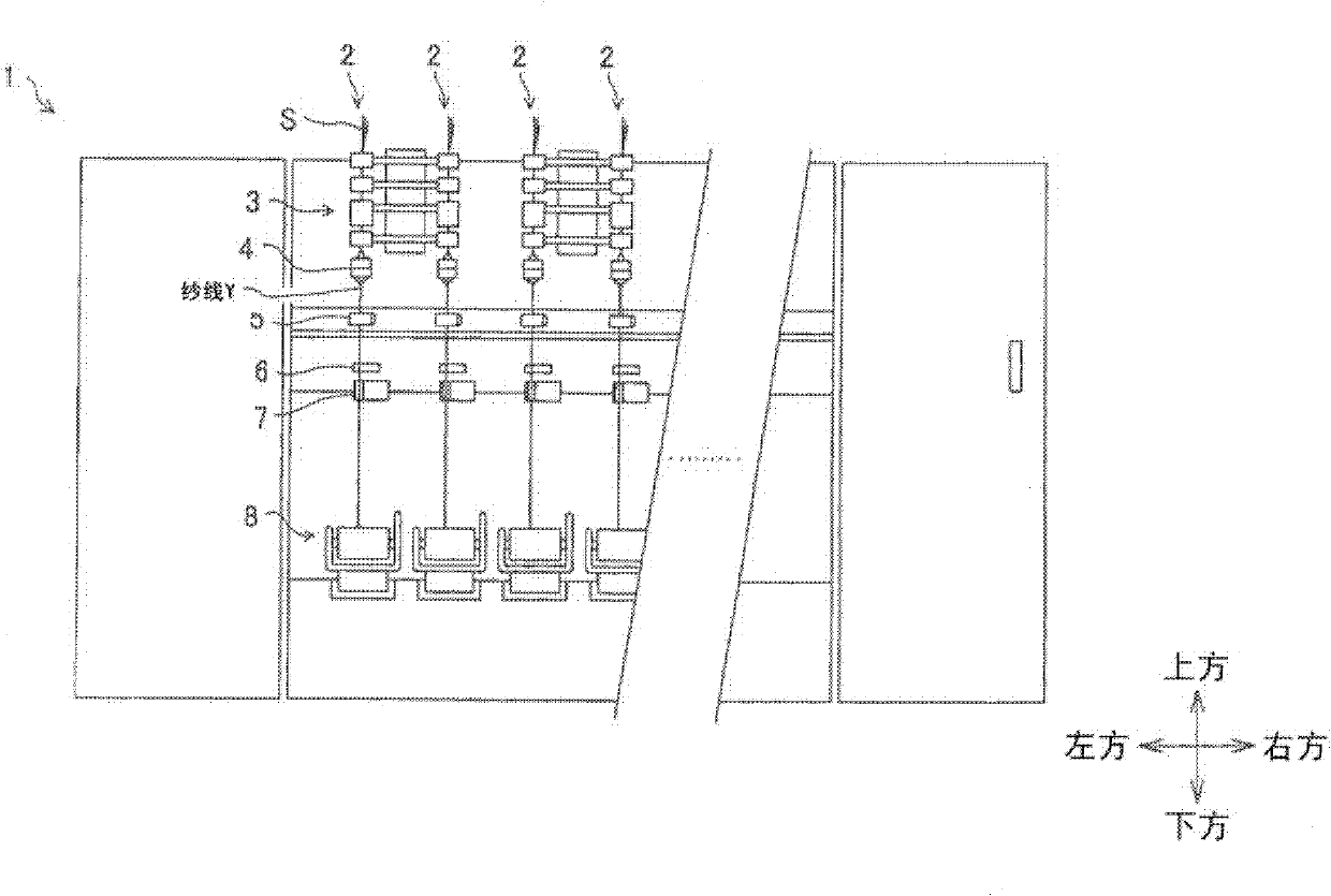
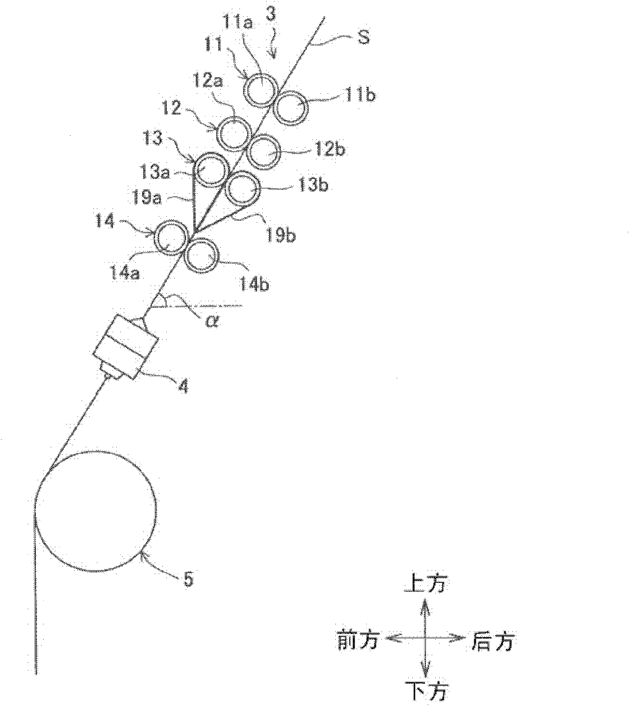
[0042] Preferred embodiments of the present invention will be described below. In addition, in the following, as shown in each figure, the front-back direction, the left-right direction, and the up-down direction which are perpendicular to each other are defined and described. Such as figure 1 As shown, in the spinning machine 1, a plurality of spinning units 2 along figure 1 arranged in the left-right direction. Each spinning unit 2 includes a drafting device 3, a spinning device 4, a yarn feeding device 5, a yarn defect detecting device 6, a yarn joining device 7, a winding device 8, and the like.

[0043] The drafting device 3 drafts the sliver S fed from above, turns it into a fiber bundle, and sends it to the spinning device 4 . The spinning device 4 air-spins the fiber bundle conveyed from the drafting device 3 into a yarn Y. The yarn feeding device 5 sends the yarn Y spun by the spinning device 4 to the winding device 8 . The yarn defect detecting device 6 detects ...


PUM


Abstract

An object is to provide a configuration that allows easy relocation of a draft roller. A spinning machine includes a frame having a sloping surface, a draft roller unit including a draft roller, and a balancing mechanism. The draft roller unit is provided on the sloping surface of the frame in a location-adjustable manner. The balancing mechanism exerts an urging force on the draft roller unit in a direction opposite to a direction in which the draft roller unit is pulled by its own gravity.

Description

technical field [0001] The present invention relates to a draft device for drafting and conveying a sliver, and a spinning machine including a draft device unit having a plurality of draft devices. Background technique [0002] The drafting device described in Japanese Patent Application Laid-Open No. 2007-182647 uses 4 pairs of drafting rollers (rear roller, third roller, intermediate roller, and front roller) to draft the sliver to form a fiber bundle and transport it to the spinning section . And, the four bottom rollers constituting these four pairs of draft rollers are rotatably supported by a support member arranged on the inclined surface, and arranged along the inclined direction of the inclined surface. [0003] In such a drafting device, it is necessary to change the distance between the drafting rollers according to the length of the sliver fiber or the like. At this time, the operator changes the position of the bottom roll by moving the support member along th...

Claims


Application Information

Patent Timeline
IPC IPC(8): D01H5/44D01H5/56
CPCD01H5/505D01H5/44
Inventor 坂元直孝
Owner MURATA MASCH LTD
Why Eureka
Try Eureka