
Temperature control valve for automatically switching flow direction according to water temperature

A technology of automatic switching and temperature control valves, applied in valve details, multi-way valves, valve devices, etc., can solve problems such as unfairness of users, waste of heat energy, and underutilization of heat energy

Active Publication Date: 2011-11-09
大同首安通科技有限公司
View PDF5 Cites 4 Cited by
  • Summary
  • Abstract
  • Description
  • Claims
  • Application Information

AI Technical Summary

Problems solved by technology

However, due to historical reasons, the existing heating system still has some defects; for example, the return water temperature of the heat medium is sometimes very high, and the heat energy is not fully utilized, so it is sent back to the boiler room by the return water pipe; The hot water to the user, although the temperature does not vary greatly, still passes through the heat meter. This defect is unfair to the user on the one hand, and on the other hand, the heat energy is not fully utilized, resulting in a waste of heat energy in essence.

Method used


Image

  • Temperature control valve for automatically switching flow direction according to water temperature
  • Temperature control valve for automatically switching flow direction according to water temperature

Examples


Embodiment Construction

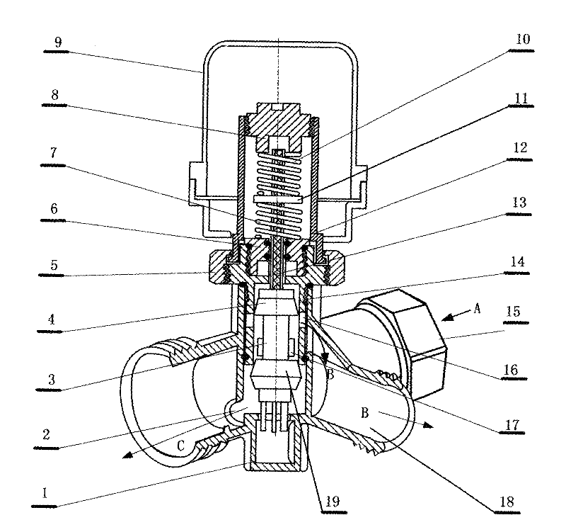
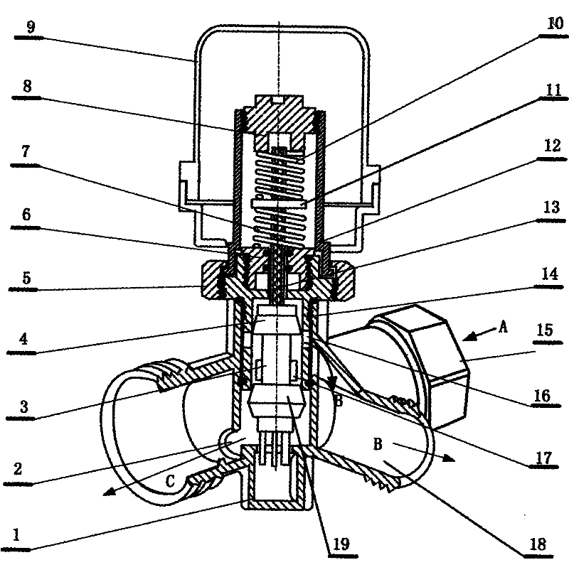
[0008] The present embodiment is shown in the drawings, and the present invention mainly includes a valve body (1), a water outlet C (2), a piston (3), an upper sealing ring (4), a connecting nut (5), a connecting cover (6), Return spring (7), adjusting nut (8), protective cap (9), thermal element (10), baffle plate (11), valve sleeve (12), linkage rod (13), valve cover (14), Water inlet A (15), water flow outlet (16), water flow inlet (17) water outlet B (18), lower sealing ring (19); valve body (1) is a three-way structure, water outlet B (18), C(2) is staggered by 90° on the valve body (1); there is a water outlet (16) on the valve cover (14), and there is a water inlet (17) below the water outlet (16); the water outlet (16) It is connected with the water outlet B (18); the water inlet (17) is connected with the water inlet A (15), and the through hole at the lower end of the valve cover (14) is connected with the water outlet (2); the water inlet A (15) is connected with t...


PUM


Abstract

The invention relates to a temperature control valve for automatically switching a flow direction according to a water temperature and belongs to the field of manufacturing of water heating equipment. The temperature control valve is characterized in that: a water flow outlet is formed in a valve cover; a water flow inlet is formed below the water flow outlet; the water flow outlet is communicated with a water outlet B; the water flow inlet is communicated with a water inlet A; and a through hole at the lower end of the valve cover is communicated with a water outlet C. By the temperature control valve, a higher-temperature thermal medium flowing out of radiating equipment is conveyed back to the radiating equipment, the aim of repeated heat utilization is fulfilled, and backwater at a low temperature is directly conveyed back to a boiler room; and when the device automatically switches the flow direction, external power is not needed.

Description

technical field [0001] The invention relates to a temperature control valve for automatically switching the flow direction according to the water temperature, which belongs to the field of plumbing equipment manufacturing. Background technique [0002] The existing winter heating, due to the adoption of more advanced technologies such as installing heat meters, effectively controls the indoor temperature and reduces the waste of heat energy a lot. However, due to historical reasons, the existing heating system still has some defects; for example, the return water temperature of the heat medium is sometimes very high, and the heat energy is not fully utilized, so it is sent back to the boiler room by the return water pipe; The hot water to the user, although the temperature does not vary greatly, still passes through the heat meter. This defect is unfair to the user on the one hand, and on the other hand, the heat energy is not fully utilized, resulting in a waste of heat ene...

Claims


Application Information

Patent Timeline
Patent Type & Authority Applications(China)
IPC IPC(8): F16K11/04F16K31/70F16K27/02
Inventor 全龙浩
Owner 大同首安通科技有限公司
Learn More