Mold structure with glue-feeding rear mold
A technology of mold and back mold, which is applied in the mold structure field of back mold injection, which can solve the problems of high appearance requirements and failure to meet the appearance requirements of injection molding products.
Inactive Publication Date: 2011-11-16
VANGUARD TECH WUXI
View PDF0 Cites 4 Cited by
- Summary
- Abstract
- Description
- Claims
- Application Information
AI Technical Summary
Problems solved by technology
[0002] Existing appearance products have high requirements on the appearance of the exposed parts, such as notebook casings, and the existing front mold injection molds cannot meet the appearance requirements of their injection molding products
Method used
View moreImage
Smart ImageViewing Examples
Examples
Embodiment Construction
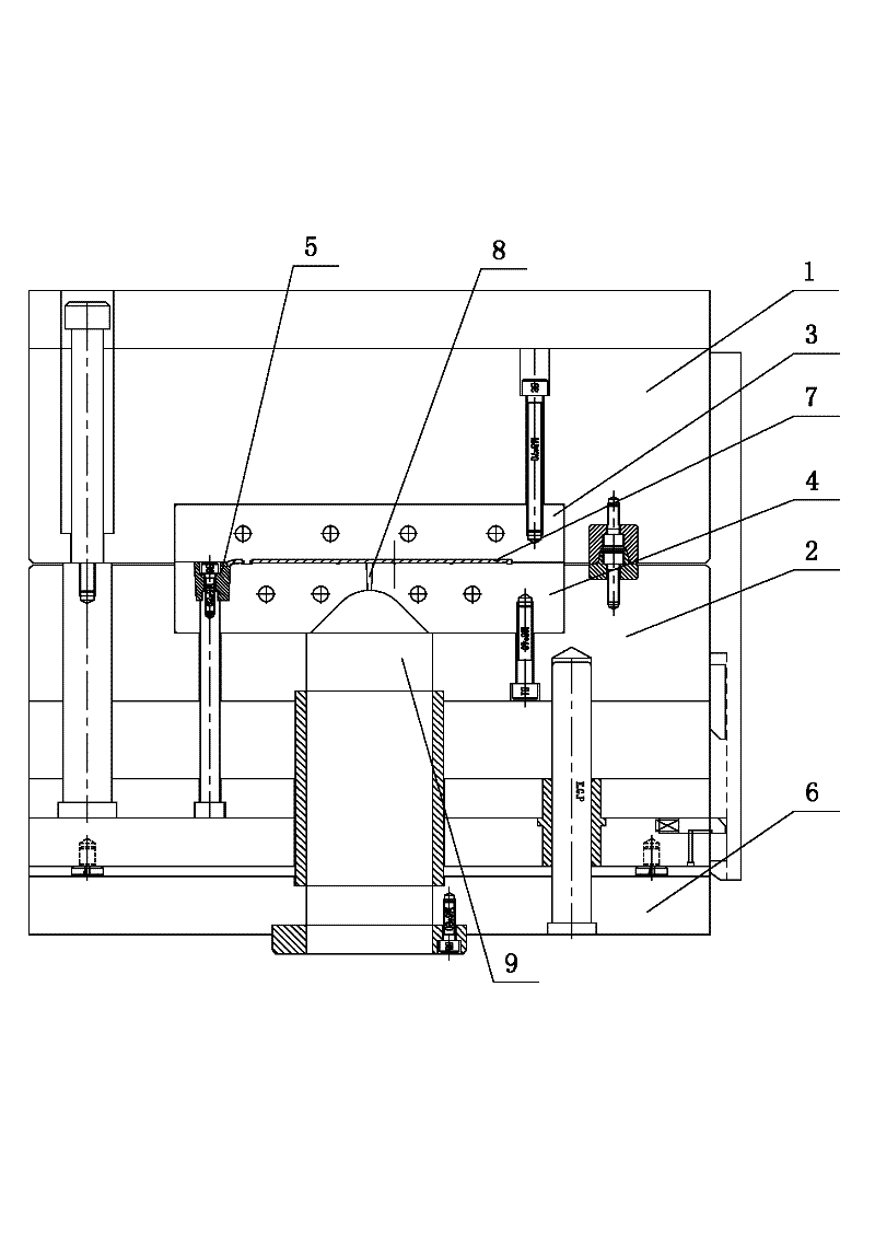
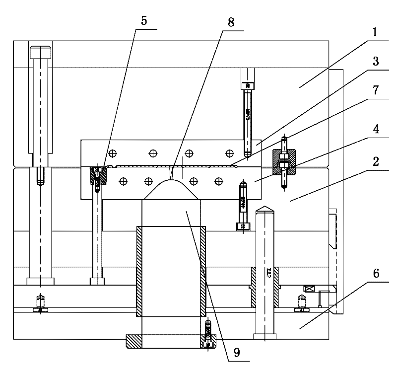
[0007] See figure 1 , which includes A plate 1, B plate 2, front mold 3, back mold 4, insert 5, bottom plate 6, the cavity between the front mold 3, back mold 4, and insert 5 is a mold cavity, and inside the mold cavity is The product 7 is provided with a glue inlet 8 on the rear 4, and the glue inlet 8 is connected to the injection nozzle 9 of the injection molding machine.
Login to View More PUM
 Abstract
The invention provides a mold structure with a glue-feeding rear mold. By the mold structure, the aesthetic appearance of a part exposed out of a product is ensured, and apparent visual requirements are met. The mold structure comprises a plate A, a plate B, a front mold, a rear mold, an insert and a bottom plate, wherein a cavity among the front mold, the rear mold and the insert is a die cavity. The mold structure is characterized in that: a glue-feeding hole is formed in the rear mold and is communicated with an injection molding nozzle of an injection molding machine; and the injection molding nozzle is positioned at the lower end of the die cavity and is fastened to the bottom plate.
Description
technical field [0001] The invention relates to the structural technical field of product molds, in particular to a mold structure for back mold injection. Background technique [0002] Existing appearance products have high requirements on the appearance of the exposed parts, such as notebook casings, and the existing front-mold injection molds cannot meet the appearance requirements of the injection molding products. Contents of the invention [0003] The invention provides a mold structure with glue feeding in the back mold, which ensures the beautiful appearance of the exposed part of the product and meets the visual requirements of the appearance. [0004] The mold structure of back mold feeding, it comprises A plate, B plate, front mold, back mold, insert, base plate, the cavity between described front mold, back mold, insert is mold cavity, it is characterized in that: A glue inlet is opened on the rear mold, and the glue inlet communicates with the injection nozzl...
Claims
Login to View More Application Information
Patent Timeline
 Patent Type & Authority Applications(China)
IPC IPC(8): B29C45/26
Inventor 张卫
Owner VANGUARD TECH WUXI
Features
- R&D
- Intellectual Property
- Life Sciences
- Materials
- Tech Scout
- Unparalleled Data Quality
- Higher Quality Content
- 60% Fewer Hallucinations
Learn More Browse by: Latest US Patents, China's latest patents, Technical Efficacy Thesaurus, Application Domain, Technology Topic, Popular Technical Reports.
© 2025 PatSnap. All rights reserved.Legal|Privacy policy|Modern Slavery Act Transparency Statement|Sitemap|About US| Contact US: help@patsnap.com


