
foil beat device

A technology of applying device and transfer foil, which is applied in printing, rotary printing machine, printing machine, etc., can solve the problems of position change, tension change, influence on belt tension itself, etc., and achieve the effect of high takt speed

Active Publication Date: 2015-08-26
HEIDELBERGER DRUCKMASCHINEN AG
View PDF6 Cites 0 Cited by
  • Summary
  • Abstract
  • Description
  • Claims
  • Application Information

AI Technical Summary

Problems solved by technology

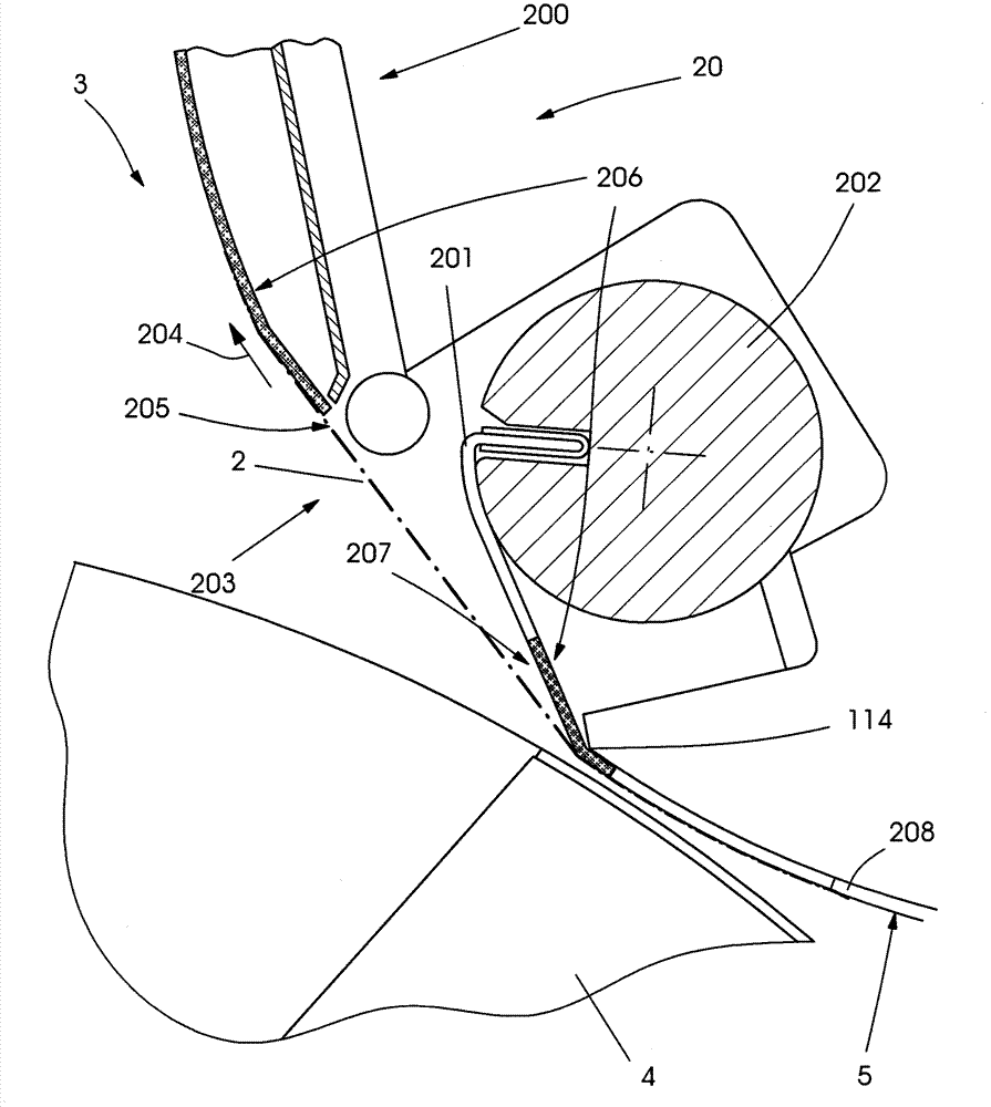
[0009] But there is still the problem of at least a short-term change in position and a change in tension of the foil itself in the channel
Since the transfer foil is carried along by said edge area of ​​the channel, the belt tension itself is significantly affected

Method used


Image

  • foil beat device
  • foil beat device
  • foil beat device

Examples


Embodiment Construction

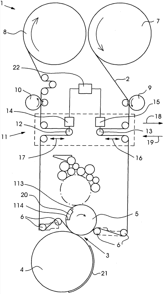
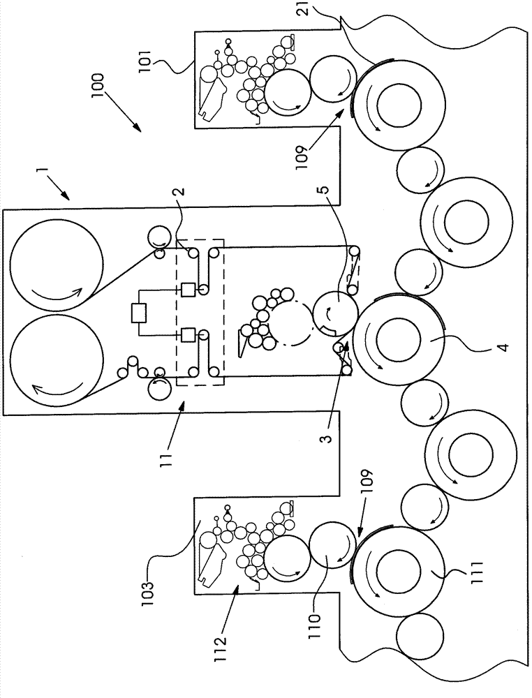
[0021] figure 1 shows a foil transfer device 1 in which a transfer foil 2 is guided through a transfer nip 3 .

[0022] The transfer nip 3 is formed by a transfer cylinder 5 and an impression cylinder 4 . The transfer foil 2 is unwound from the supply roll 7 and pulled by a front puller 9 in the direction of the transfer nip 3 . The supply roll 7 rests on a friction shaft (not shown here) and is driven at a speed that is lower than the speed of the printing material 21 . The drive of the supply roll 7 takes place via a friction shaft. The transfer foil 2 is drawn off the supply roll 7 via the front puller 9 , the rollers of the front puller 9 being driven at a speed higher than the friction shaft speed of the supply roll 7 . However, the front drawer 9 always works at a speed that is lower than the speed of the printing material 21 .

[0023] The unwound transfer foil 2 is guided through the transfer nip 3 via the front float 13 of the clock module 11 and via the further d...


PUM


Abstract

The device has an applicator for applying adhesive to a printing material, and a foil transfer unit arranged downstream of the applicator. The transfer unit has a transfer gap (3) for transferring a transfer layer from a transfer film (2) to the material, where the gap is formed by a transfer cylinder (5) and an impression cylinder (4). The film is guided around the transfer cylinder that comprises a channel (20). A strip (206) i.e. adhesive strip, made from silicone or PTFE is provided in an area of the channel for reducing the adhesion of a rear side of the film to the transfer cylinder.

Description

technical field [0001] The invention relates to a foil transfer device comprising: an applicator for at least regionally loading a printing material guided through the applicator with adhesive; a transfer foil with a transfer nip supported downstream of the applicator Device for at least regional transfer of a transfer layer from a carrier foil to the printing material, the transfer layer and the carrier foil together forming a transfer foil, wherein the transfer nip is passed through a transfer cylinder and an impression cylinder Formed, the transfer foil is guided at least partially around the transfer cylinder, and the transfer cylinder has channels. Background technique [0002] Foil transfer devices of the described type are used in the finishing of printed products, for example in order to produce gloss effects. This machine can be divided into hot embossing film machine and cold film embossing machine. In cold film embossing presses, the transfer layer is transferre...

Claims


Application Information

Patent Timeline
Patent Type & Authority Patents(China)
IPC IPC(8): B41F16/00
CPCB41P2219/20B41F16/00B41P2219/51B41F19/004B41F19/062
Inventor A·韦伯
Owner HEIDELBERGER DRUCKMASCHINEN AG
Learn More