Double-row waste winding mechanism for label punching

A rewinding mechanism and waste rewinding technology, which are used in thin material processing, coiling strips, conveying filamentous materials, etc., can solve the problems of inability to remove the annular waste belt, large tension changes, etc., and achieve the transformation cost. Low cost, high economic value, the effect of maintaining reliability

Pending Publication Date: 2022-07-29
昆山盛格纳电子材料有限公司
View PDF0 Cites 0 Cited by
  • Summary
  • Abstract
  • Description
  • Claims
  • Application Information

AI Technical Summary

Problems solved by technology

[0006] The purpose of the present invention is to solve the above-mentioned deficiencies in the prior art. Aiming at the problem that the traditional ring-shaped waste tape is removed synchronously, ther

Method used


Image

  • Double-row waste winding mechanism for label punching
  • Double-row waste winding mechanism for label punching
  • Double-row waste winding mechanism for label punching

Examples


Example Embodiment

[0051] Example 1

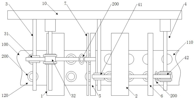
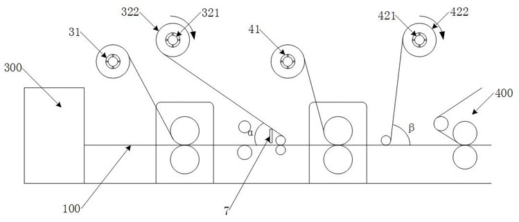
[0052] like figure 2 As shown, the first tape rewinding portion 32 includes a first rotating shaft 321 provided with a rotational drive source and a first reeling reel 322 provided on the first rotating shaft, and the second tape rewinding portion 42 includes a rotating drive source. The second rotating shaft 421 and the second winding material shaft 422 arranged on the second rotating shaft.

[0053] That is, two independent drive source rotating shafts are used to meet the needs of independent tension control and stable winding.

Example Embodiment

[0054] Embodiment 2

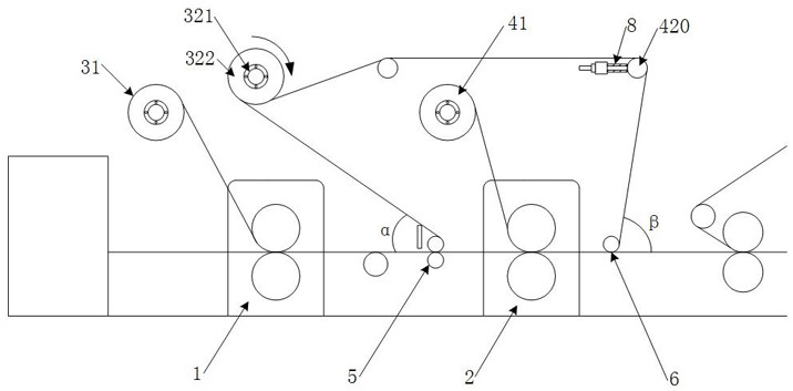
[0055] like image 3 As shown, the first tape rewinding part 32 includes a first rotating shaft 321 with a rotational drive source and a first reeling material shaft 322 provided on the first rotating shaft, and the second tape rewinding part 42 includes a first reeling shaft 322 provided on the first rotating shaft A second reel spool 422 on the rotating shaft and several steering shafts 420 for tape steering. Either steering shaft has a tension adjustment displacement.

[0056] Specifically, a rotating shaft is used to realize the synchronous tape rewinding of double-row waste materials, so that the cost can be controlled. At the same time, by adjusting the displacement of the tension of the steering shaft, it can meet the matching requirements of different strokes of the tape tension, making the rewinding operation more stable and reliable. .

[0057] The steering shaft 420 is realized by a floating tension control part 8 with a linear floating disp...


PUM


Abstract

The invention discloses a double-row waste winding mechanism for label punching, which comprises a first film clamping roller, a second film clamping roller, a first waste winding mechanism and a second waste winding mechanism, and is characterized in that the first waste winding mechanism comprises a first adhesive tape unwinding part and a first adhesive tape winding part; an adhesive tape of the first adhesive tape unwinding part is pressed and attached to a first column of labels through a first film clamping roller and adheres to annular waste to be connected into the first adhesive tape winding part, and the second waste winding mechanism comprises a second adhesive tape unwinding part and a second adhesive tape winding part. And an adhesive tape of the second adhesive tape unwinding part is pressed and attached to the second column of labels through the second film clamping roller, adheres to the annular waste and is connected to the second adhesive tape winding part. The double-row annular waste is subjected to adhesive tape pasting and rolling respectively, the tension influence of stripping force on a composite material belt is reduced, independent stripping and rolling are more reliable and stable, and effective operation of waste rolling is maintained. And a differential steering angle winding design is adopted, so that old equipment is easy to transform, and the double-wire stripping winding reliability is maintained under the condition that the space is limited.

Description

technical field [0001] The invention relates to a double-row waste rewinding mechanism for label punching, belonging to the technical field of label punching and removing waste. Background technique [0002] A label is a piece of paper that is attached or tied to an item and indicates the name, purpose, price, etc. of the item. The physical label is a brief sign used to indicate the name, weight, volume, use and other information of the item. There are traditional printed labels and modern barcode printed labels. The identification pattern is formed on the label tape by printing or printing. [0003] Generally, the label is printed or formed by printing on the material tape. The material tape includes a composite label material tape and a release material tape. After the label material tape is completed, the outer contour of the label on the label material tape needs to be punched, and then The scrap rewinding mechanism is used to remove the scrap after punching, and fina...

Claims


Application Information

Patent Timeline
IPC IPC(8): B65H18/10B65H69/00B65H23/26
CPCB65H18/10B65H69/00B65H23/26
Inventor 杨帅孟密山李明明
Owner 昆山盛格纳电子材料有限公司
Why Eureka
Try Eureka