Endovascular medical device with plurality of wires

a medical device and plurality of wires technology, applied in the field of medical devices, can solve the problems of increasing the difficulty of advancing the central member through the catheter lumen, affecting the stability of the catheter,

Inactive Publication Date: 2006-04-11
COOK MEDICAL TECH LLC
View PDF86 Cites 110 Cited by
  • Summary
  • Abstract
  • Description
  • Claims
  • Application Information

AI Technical Summary

Benefits of technology

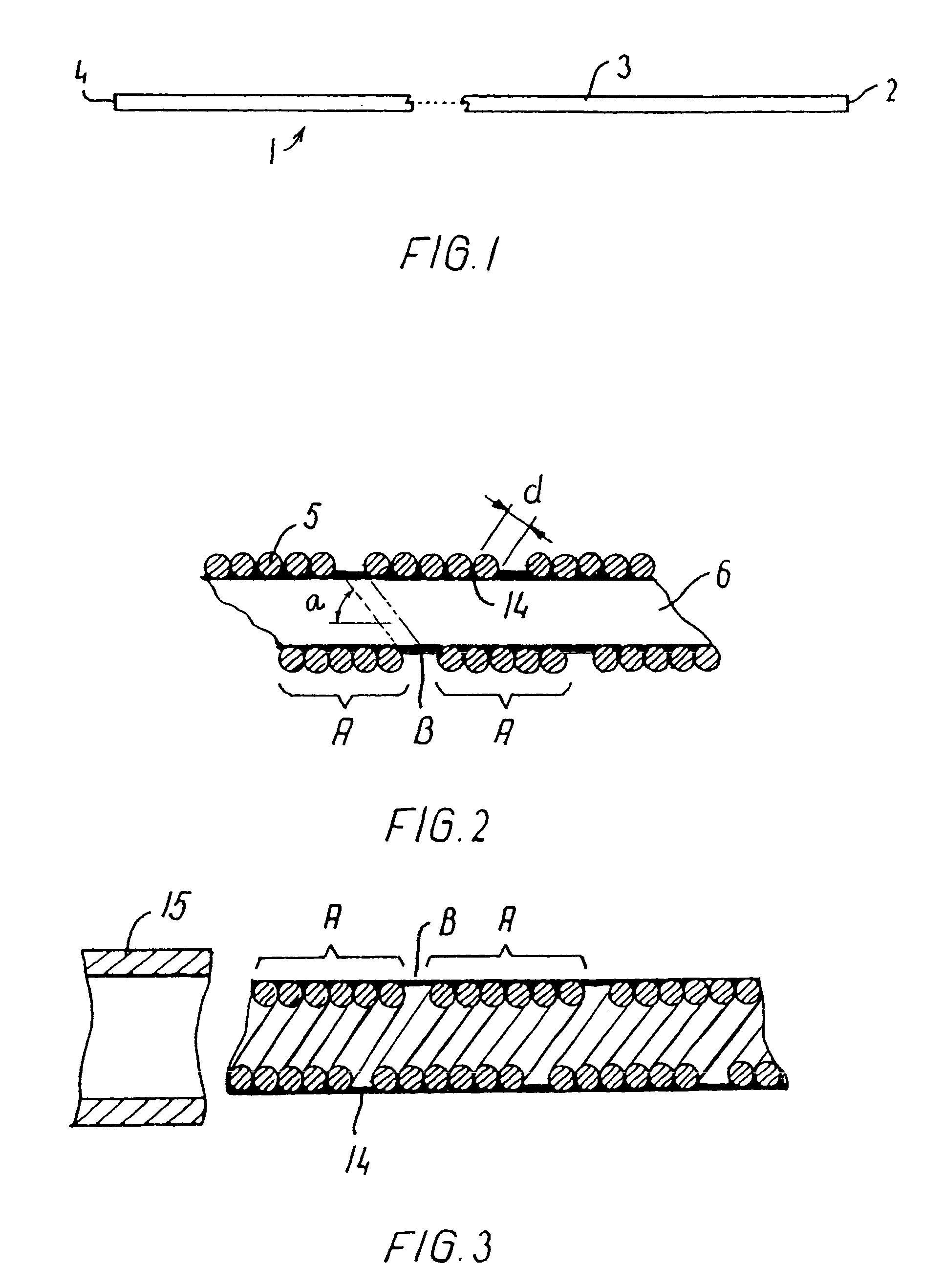
[0014]The wound wires transfer torque and also force components directed in the axial direction of the medical device to the distal end thereof, and this construction is found to give a very high resistance to kinking of the medical device. When a catheter according to the present invention is heavily bent, the cross-section of the catheter maintains a circular shape. This provides a distinct advantage over prior art catheters which are deformed into an oval shape in cross-section when bent leading to kinking. The catheter surprisingly maintains its capabilities for transferring torque and push when it follows a tortuous path involving two or more loops, probably because of the excellent kinking resistance. These qualities facilitate placement of the catheter at the desired position in the vascular system, and by making the catheter system so that the inner surface of the catheter is mainly undeformable by a central member moving axially therewithin, it is virtually impossible for the central member to get stuck in the catheter wall, even in situations where the catheter is heavily curved. This is in contrast to prior art coaxial systems where the catheter is made of a soft material such as a resin, the inner surface of which is readily deformable in a local area, causing the formation of a small bead in front of the tip of the central member bearing against the wall of the curved catheter. It is an advantage of the catheter according to the present invention that the wall is primarily made of wires that provide a hard and relatively slippery inner surface resulting in low resistance to advancing the central member through the lumen of the catheter.
[0015]The inventive catheter maintains three valuable characteristics of very high flexibility, pushability and torqueability even when set in a very tortuous pattern involving two or more tight loops, and the catheter can thus be of use in very small and distant vessels such as deep brain sites accessed by intracranial catheterization. Preferably, a thin sealing coating of elastic, low-friction material, or adhesive material may be provided over the outwardly directed surfaces of the coiled wires or along the inner surfaces that define a lumen, or at least in recesses between abutting wires or in interstices between nonabutting turns between the groups of wires, thus sealing the interstices between the wires so that the catheter wall is leakproof especially where the device is a catheter or sheath.
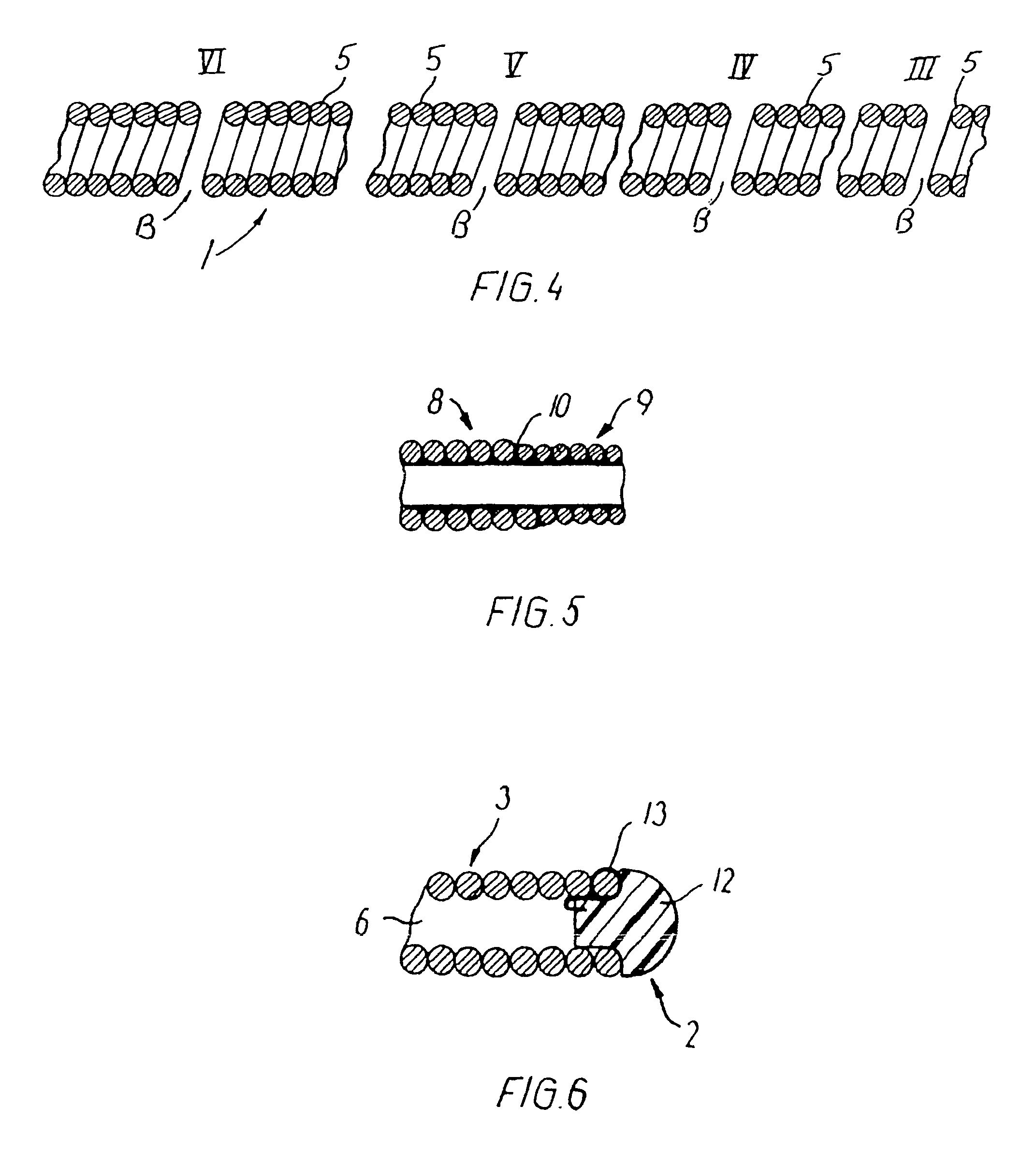
[0018]In another aspect, the number of wires may vary along the length of the catheter, such as reducing the number of wires in the row during the winding operation in the distal direction, enabling a larger pitch angle and increasing the flexibility of the catheter proximate to the distal end.
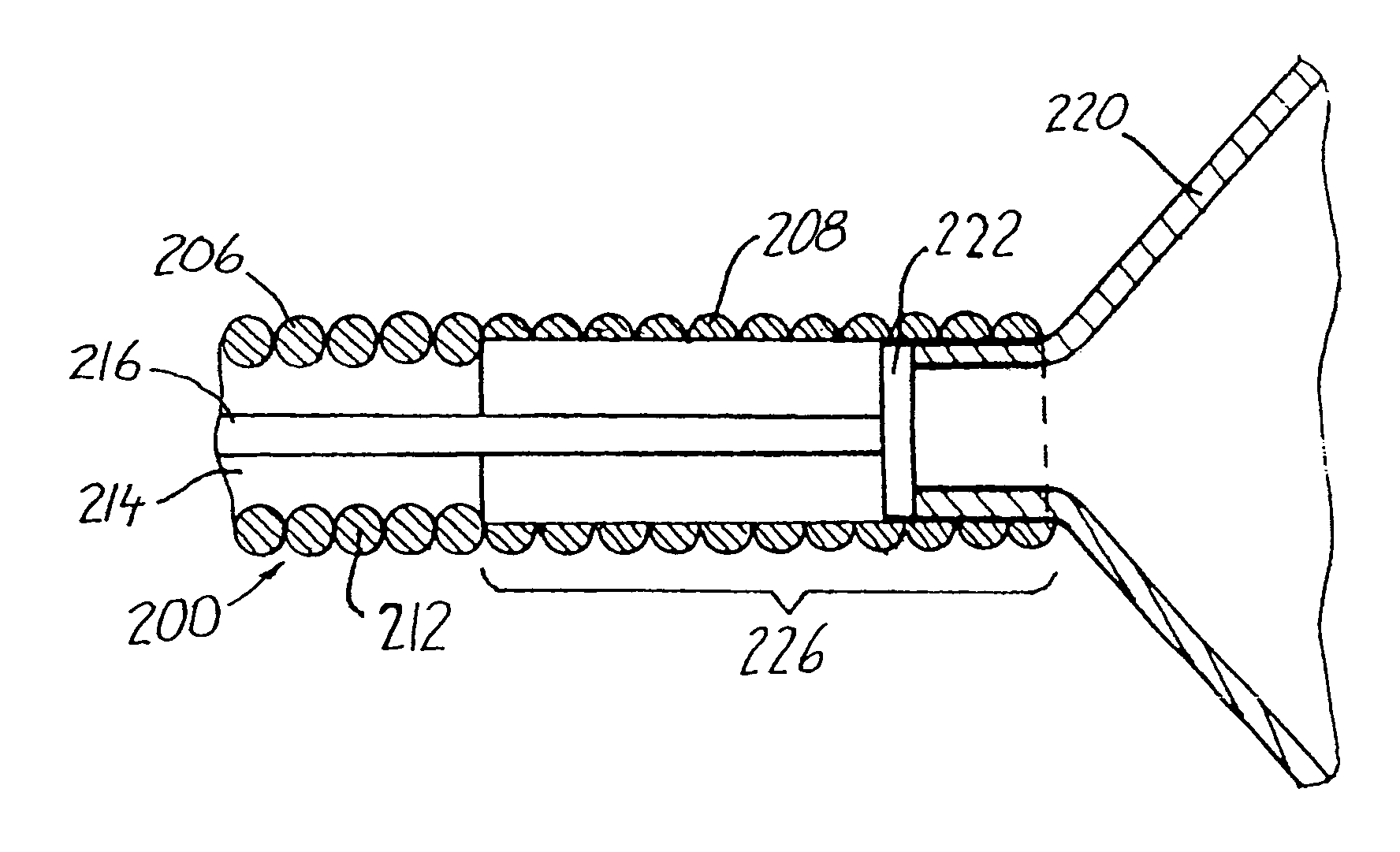
[0020]In a third embodiment, a prosthesis receptacle is a separate member and is fixed to the helically wound multiple filament row of wires of the catheter shaft, in axial extension thereof. This allows the prosthesis receptacle to be designed and manufactured independently of the shaft portion. The mounting in direct extension of the wire or wires of the catheter shaft makes the prosthesis receptacle follow torsional actions on the shaft portion. Although the prosthesis receptacle can be designed in any manner capable of resisting the outward pressure applied to the inside of the receptacle by the compressed prosthesis, it is preferred that the prosthesis receptacle be a tubular segment of multiple filament construction, such as a braided wire construction providing the prosthesis receptacle with a high flexibility. More preferably, the receptacle is a construction of a second helically wound group or row of multiple wires; this makes it possible to obtain a very diminutive outer diameter as only a single layer of wires is required.
[0022]In still another embodiment, the medical device may be used in an introducer for an embolization device, where the delivery member comprises primarily a plurality of wires to provide the advantageous torqueability of the present invention. The distal end of the delivery member thus is able to be rotated from rotation of the proximal end thereof, and thus being disconnectable through unscrewing from the embolization device, a technique that causes only negligible influence on the vasculature while enabling precise maintenance of the embolization device in its desired position during detachment even in very tortuous paths to treatment sites such as intracranial locations.

Problems solved by technology

The more tortuous the path and the smaller the catheter the more difficult it is to advance the central member through the catheter lumen.
This difficulty is in particular pronounced in coaxial systems for intracranial use.
Where the central member is a delivery device for an embolization coil and must be rotated to disconnect from the coil upon release at the treatment site, the central member must be capable of transmitting torque to its distal end for assured coil disconnection; one such prior art coil delivery system is disclosed in U.S. Pat. No. 5,122,136; but it is a common problem that such prior art coil delivery members have relatively high rigidity which is problematic in small or tortuous vessels with aneurysms.

Method used


Image

  • Endovascular medical device with plurality of wires
  • Endovascular medical device with plurality of wires
  • Endovascular medical device with plurality of wires

Examples


example 1

[0078]A catheter was made of a helically wound row of four wires of 0.35 mm wire diameter. The body portion of wound wires had initially an outside diameter of 1.67 mm and an inner lumen of 0.97 mm. A coating of PTFE of a minimum thickness of 0.1 mm was applied onto the inside of the catheter. The catheter was set in a complex curved shape involving three consecutive loops of a loop diameter of 24 mm axially separated by two loops of a loop diameter of 18 mm and a number of further turns representative of a complex vascular structure. Then the body portion of the catheter was manipulated and it proved to be easily pushed forward and retracted as well as easily torqued. Then a guidewire was pushed forwardly in relation to the body portion, and it proved to be easily pushed out past the distal end of the catheter without causing noticeable flexion or movement of the catheter.

example 2

[0079]A catheter was made of a helically wound row of five wires of 0.30 mm wire diameter. The winding of a first segment of the body portion was made with an outside diameter of 1.20 mm and an inner lumen of 0.6 mm. Another segment was made up of a second helically wound row of four wires of 0.15 mm wire diameter. This segment had a length of 20 cm and an outside diameter of 1.20 mm and an inside diameter of 0.9 mm. The segments were joined by laser welding. The catheter body was provided with a flexible coating on its outside. The catheter was advanced through a complex curved vascular system involving several consecutive retrograde turns in vessels having a lumen of only 2 mm and less. Then the catheter was torqued and moved both forwardly and backwardly without any problems.

example 3

[0080]A catheter was made of a first helically wound row of eight wires of 0.075 mm wire diameter. The winding was made with an outside diameter of 0.25 mm and an inner lumen of 0.1 mm. The body portion had a length of 160 cm and was coated with a hydrophilic material of polyacrylamide on its outside surface. When tested the catheter shows no problems. After placing the catheter in a very complex pattern involving several sharp turns (see an example in FIG. 9), a guidewire could be advanced with only very low friction, and after removal of the guidewire, a fluid could be injected through the catheter without leakage through the coating.

[0081]When the catheter is to be introduced into the vascular system there is firstly established a percutaneous puncture site, e.g., by the Seldinger technique, or an existing puncture site is used. Then the body or shaft portion of the catheter is inserted through the cannula, sheath or hemostatic valve at the puncture site and the catheter is advan...


PUM

PropertyMeasurementUnit
pitch angleaaaaaaaaaa

Abstract

An endovascular device (1, 100, 200, 300) having a distal end (2), a proximal end (4) and a body portion (3) therebetween. The body portion is made of a multiple filament helically wound row (A) of wires (5), provided with a sealing coating (14) on the inside surface or the outside surface or both. The device may be a catheter (1), a sheath, an introducer, a delivery device, a pusher (100), an embolization coil delivery device (300), or a receptacle (208) for an expandable prosthesis (220) used with a delivery device (200). From 2 to 12, and preferably from 4 to 8, wires (5) are used in the row, and fewer wires may be used proceeding toward the distal end (2) for greater flexibility. The helically wound row of wires transmits torque and provides pushability to the device while resisting kinking, and enables a small outside diameter for reaching very small vessels and extending through very tortuous vessels.

Description

CROSS-REFERENCE TO RELATED APPLICATIONS[0001]This application is a divisional application of U.S. Pat. No. 6,589,227 issued Jul. 8, 2003.[0002]This application claims priority of the following European applications:[0003]Serial No. 00610012.7filed Jan. 28, 2000Serial No. 00610013.5filed Jan. 28, 2000Serial No. 00610014.3filed Jan. 28, 2000Serial No. 00610015.0filed Jan. 28, 2000TECHNICAL FIELD[0004]The present invention relates to the field of medical devices and more particularly to vascular devices such as catheters and delivery systems for implantable devices.BACKGROUND OF THE INVENTION[0005]Catheters for medical diagnostic or therapeutic use are well known. A catheter has a distal end and a proximal end, with a body extending therebetween and a lumen extending therethrough from end to end. A wide variety of catheters exists for percutaneous insertion by the Seldinger technique into the vascular system to accomplish diagnostic or therapeutic objectives. The vessels of the periphe...

Claims


Application Information

Patent Timeline
Patent Type & Authority Patents(United States)
IPC IPC(8): A61M25/00A61B17/12A61B19/00A61F2/95A61M25/01A61M25/09
CPCA61B17/12022A61B17/12113A61B17/1214A61M25/0043A61M25/0053A61M25/09A61F2/95A61B19/54A61B2017/1205A61B2017/12063A61B2017/12095A61M25/0009A61M25/0045A61M2025/09191A61B90/39
Inventor KLINT, HENRIK SONDERSKOV
Owner COOK MEDICAL TECH LLC
Why Eureka
Try Eureka