
Radio frequency (rf) signal generator and method for providing test signals for testing multiple RF signal receivers

一种信号接收器、测试信号的技术,应用在仪器、测量电、测量装置等方向,能够解决昂贵、限制制造需求等问题

Inactive Publication Date: 2011-11-16
LITEPOINT CORP
View PDF5 Cites 13 Cited by
  • Summary
  • Abstract
  • Description
  • Claims
  • Application Information

AI Technical Summary

Problems solved by technology

However, conventional multi-channel GPS signal generators are more expensive than single channel generators, thereby limiting their use for more expensive manufacturing requirements where repeatable locks of GPS signals must be tested

Method used


Image

  • Radio frequency (rf) signal generator and method for providing test signals for testing multiple RF signal receivers
  • Radio frequency (rf) signal generator and method for providing test signals for testing multiple RF signal receivers
  • Radio frequency (rf) signal generator and method for providing test signals for testing multiple RF signal receivers

Examples


Embodiment Construction

[0031] The following detailed description is of exemplary embodiments of the invention with reference to the accompanying drawings. This description is intended to illustrate, not to limit the scope of the invention. Such embodiments are described in sufficient detail to enable those skilled in the art to practice the invention, and it is to be understood that other embodiments may be practiced with some modification without departing from the spirit or scope of the invention.

[0032] Throughout this specification, where there is no explicit indication to the contrary in the context, it should be understood that the various circuit elements described may be singular or plural in number. For example, the terms "circuitry" and "circuitry" may include a single component or multiple components, which may be active and / or passive and connected or coupled together (e.g., as one or more integrated circuit chips) to provide the described functionality. Additionally, the term "signa...


PUM


Abstract

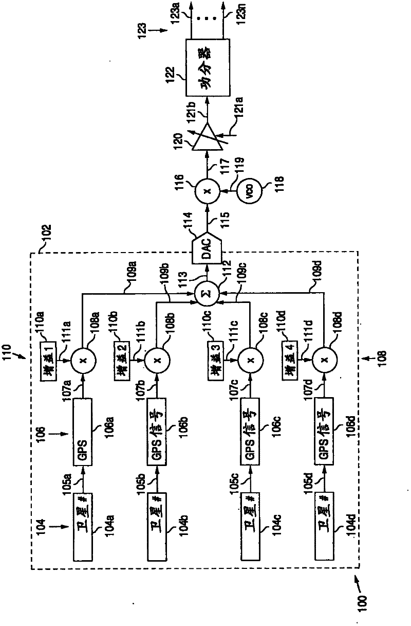
A test signal interface and method for allowing sharing of multiple test signal generators among multiple devices under test (DUTs). Digital baseband test signals generated by the multiple test signal generators are combined and converted to a baseband analog signal for conversion to a radio frequency (RF) signal for testing the multiple DUTs.

Description

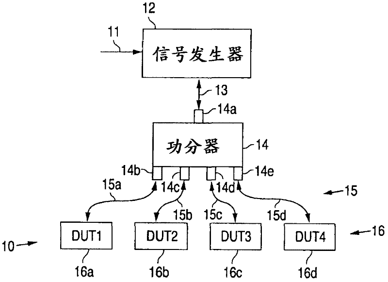
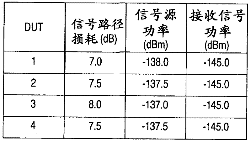
technical field [0001] The present invention relates to systems and methods for testing multiple radio frequency (RF) signal receivers, and more particularly, to testing multiple RF signal receivers using a shared RF signal generator. Background technique [0002] Manufacturing testing of RF-only systems, such as global positioning satellite (GPS) signal receivers, is typically accomplished by using a single RF signal source that is shared among multiple devices under test (DUTs). Generally, this is easy to accomplish, since the signal source typically only needs to provide a continuous signal, which also has the advantage of reducing costs. [0003] Referring to Figure 1, this test implementation uses a common RF signal source 12 that receives one or more control signals 11 depending on which input signal 13 is provided. Such a signal 13 is supplied to a 1:N (eg 1:4) power splitter 14 which divides the signal 13 (in terms of signal power) between its multiple output signal...

Claims


Application Information

Patent Timeline
Patent Type & Authority Applications(China)
IPC IPC(8): G01R31/3183G01R31/02
CPCG01S19/23
Inventor C·V·欧拉加德
Owner LITEPOINT CORP
Learn More