
Display apparatus

a display apparatus and display screen technology, applied in the direction of instruments, static indicating devices, etc., can solve the problems of not easy to achieve high-definition configuration, use of color filters, excessive specifications, etc., and achieve the effect of improving the luminance of the input video signal

Inactive Publication Date: 2008-03-20
TOSHIBA MATSUSHITA DISPLAY TECH
View PDF6 Cites 7 Cited by
  • Summary
  • Abstract
  • Description
  • Claims
  • Application Information

AI Technical Summary

Benefits of technology

[0013] According to a first aspect of the present invention, there is provided a display apparatus comprising: a video signal converter unit which converts input video signals of n colors (n is an integer equal to or larger than 2) into converted video signals of at least (n+1) colors and which generates the converted video signals of (n+1) colors t

Problems solved by technology

A method of using a color filter is at a disadvantage in that it is not easy to achieve a high-definition configuration, because a display pixel has to be composed of three color pixels.
However, in the field sequential driving method using red, green, and blue LED light sources, although a higher color gamut than in the EBU standard can be realized easily, this might leads to excessive specifications in some situations.
The field sequential driving method has the following problems: the occurrence of a monochromatic coloring phenomenon known as color breakup and a decrease in the strength of a display signal caused by time-division driving.

Method used


Image

  • Display apparatus
  • Display apparatus
  • Display apparatus

Examples


Embodiment Construction

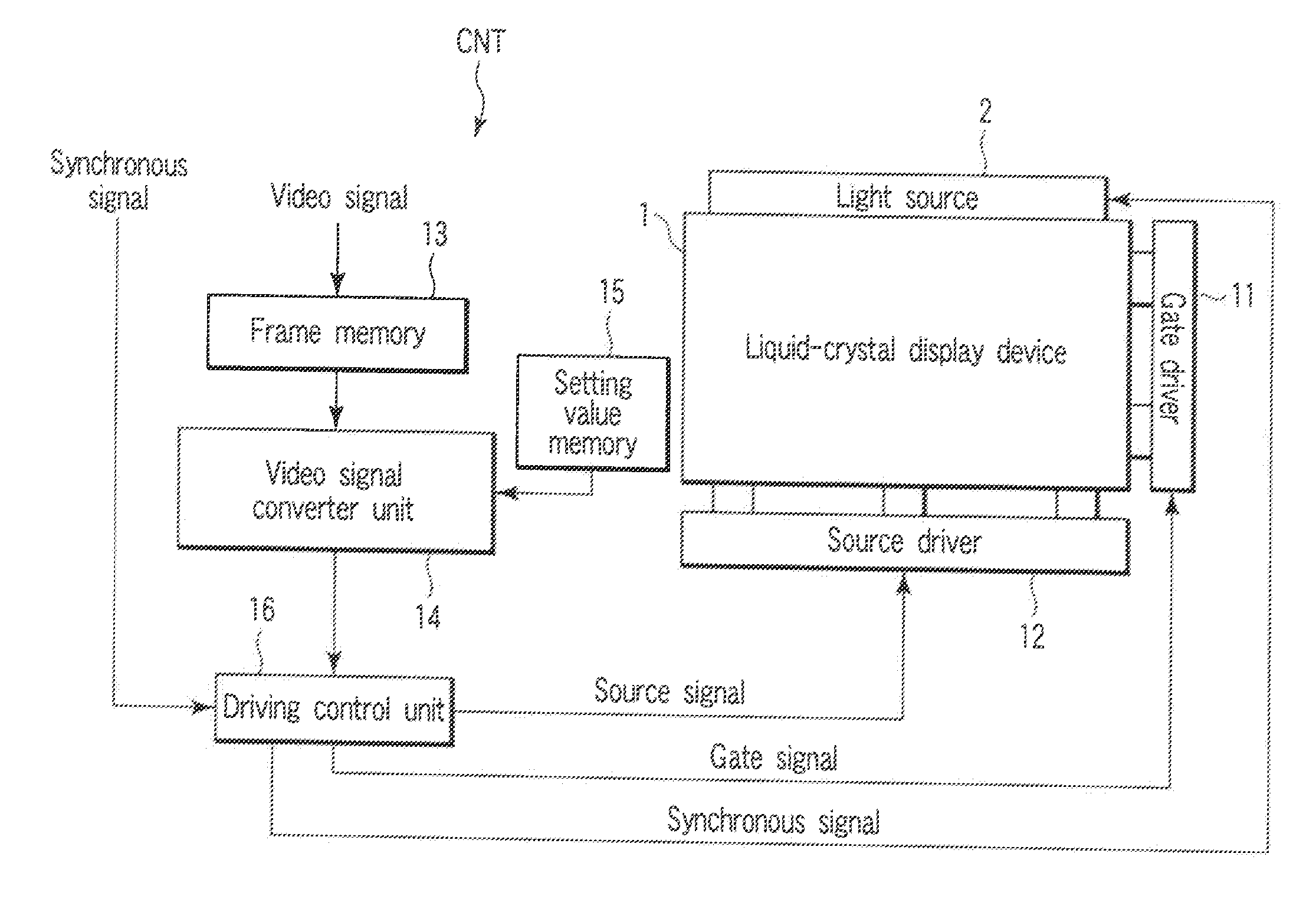
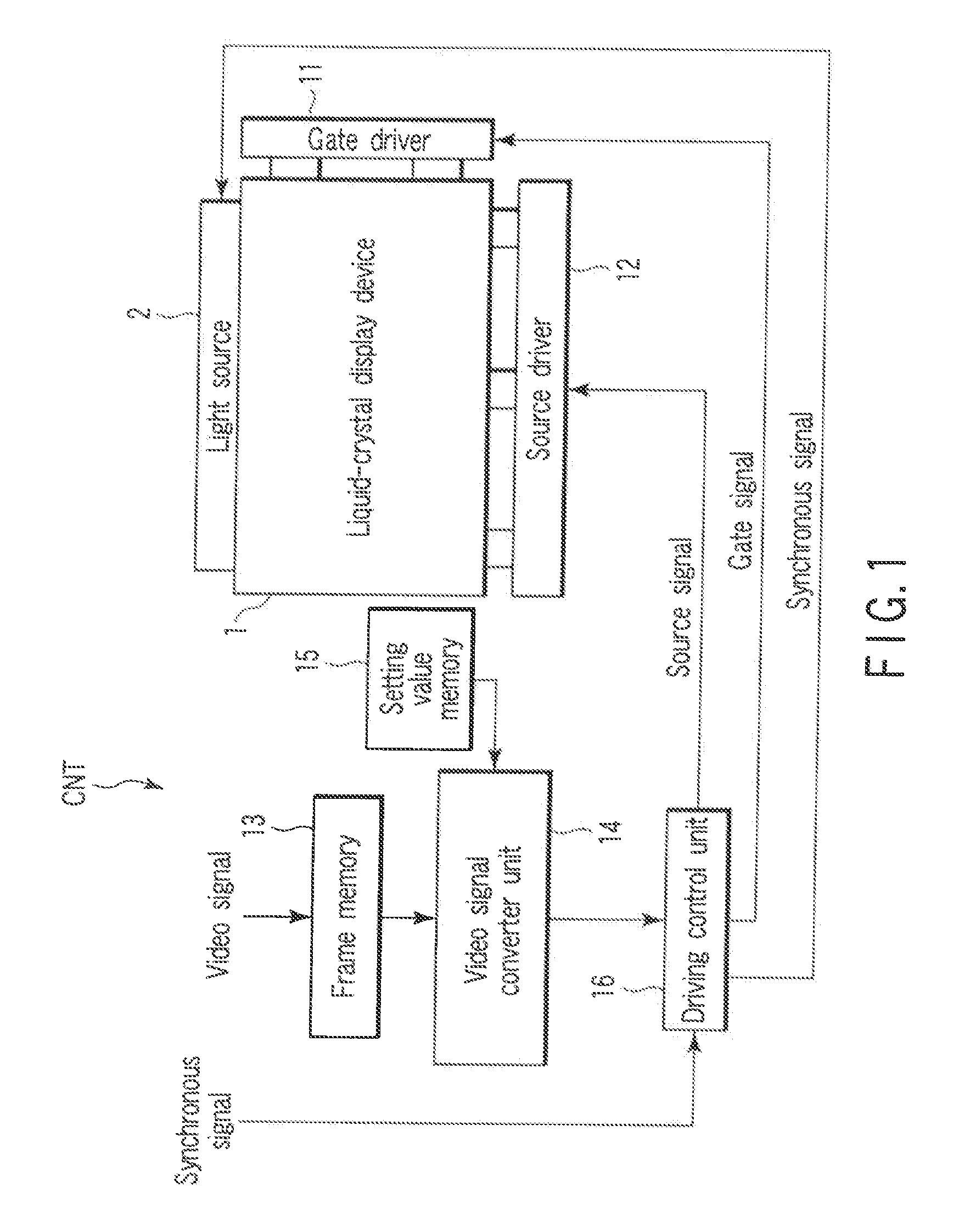
[0023]FIG. 1 is a block diagram showing the configuration of a liquid-crystal display device according to an embodiment of the invention.

[0024] The liquid-crystal display device comprises a liquid-crystal display panel 1 for displaying an image, a light source 2 for illuminating the liquid-crystal display panel 1, and a display control circuit CNT for controlling a display operation.

[0025] The liquid-crystal display panel 1 has such a structure as has a liquid-crystal layer held between an array substrate (not shown) and a counter-substrate (not shown) which makes a pair of electrode substrates. On the array substrate, a plurality of pixel electrodes arranged in a matrix are provided. On the counter-substrate, a black matrix for preventing light leakage and a counter-electrode are provided. Then, the individual pixel electrodes, individual counter-electrodes, and the liquid-crystal layer constitute the individual pixels. The liquid-crystal display panel 1 is not provided with a co...


PUM


Abstract

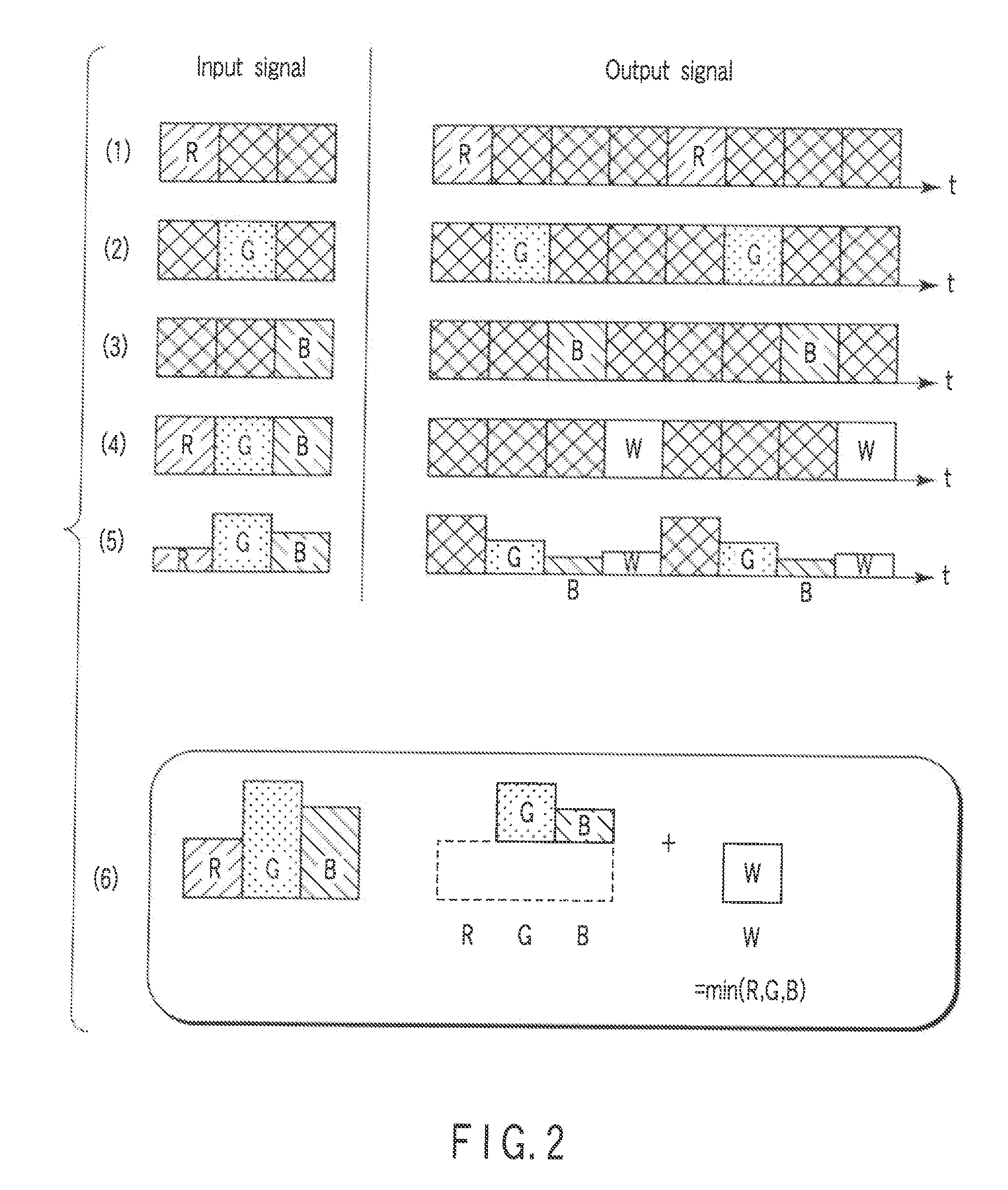
A display apparatus includes a video signal converter unit which converts input video signals of n colors (n is an integer equal to or larger than 2) into converted video signals of at least (n+1) colors, a video signal generator unit which, on the basis of the input video signal of at least one color, generates converted video signals of new (n+1) colors with the luminance of two or more converted video signals being improved, a display panel which displays (n+1) images sequentially on the basis of the converted video signals of the new (n+1) colors, and a backlight which switches between light sources of (n+1) colors for illumination sequentially in accordance with the images displayed on the display panel.

Description

CROSS-REFERENCE TO RELATED APPLICATIONS [0001] This application is based upon and claims the benefit of priority from prior Japanese Patent Application No. 2006-168772, filed Jun. 19, 2006, the entire contents of which are incorporated herein by reference. BACKGROUND OF THE INVENTION [0002] 1. Field of the Invention [0003] This invention relates to a field sequential display apparatus which creates a color display in time division, and more particularly to a display apparatus capable of adjusting the color gamut easily and creating a bright display. [0004] 2. Description of the Related Art [0005] Liquid-crystal display devices have been widely used as display panels for displaying images in computers, car navigation systems, TV sets, or the like. [0006] In a general liquid-crystal display device, to create a color display, there is provided a color filter composed of, for example, colored layers of three primary colors: red (R), green (G), and blue (B). The RGB colored layers are ar...

Claims


Application Information

Patent Timeline
IPC IPC(8): G09G3/36
CPCG09G3/2003G09G3/3607G09G2340/06G09G2320/0666G09G2310/0235
Inventor ARAKI, SHIGESUMINISHIYAMA, KAZUHIROOKITA, MITSUTAKA
Owner TOSHIBA MATSUSHITA DISPLAY TECH
Learn More