Bottom independent evacuation safety passage structure for single-hole double-track magnetic levitation tunnel

A safety channel, single-hole double-line technology, applied in safety devices, mining equipment, earthwork drilling and mining, etc., can solve problems such as poor evacuation capacity, inability to set up evacuation space, difficulty in ventilation and rescue, etc.

A safety channel, single-hole double-line technology, applied in safety devices, mining equipment, earthwork drilling and mining, etc., can solve problems such as poor evacuation capacity, inability to set up evacuation space, difficulty in ventilation and rescue, etc.

CN102251802AInactive Publication Date: 2011-11-23SHANGHAI MAGLEV TRANSPORTATION DEVELOPMENT CO LTD +1

Image

  • Bottom independent evacuation safety passage structure for single-hole double-track magnetic levitation tunnel
  • Bottom independent evacuation safety passage structure for single-hole double-track magnetic levitation tunnel
  • Bottom independent evacuation safety passage structure for single-hole double-track magnetic levitation tunnel

Examples


Embodiment Construction

[0021] based on the following Figure 2 ~ Figure 4 , specify the preferred embodiment of the present invention:

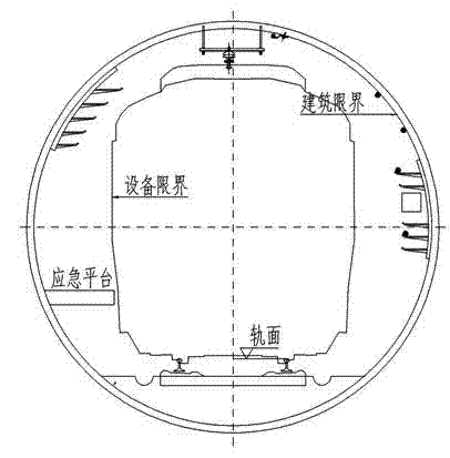
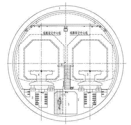
[0022] Such as figure 2 with image 3 As shown, it is a cross-sectional view of the bottom independent evacuation safety passage structure for a single-hole double-line maglev tunnel. The bottom independent evacuation safety passage structure is arranged in the tunnel segment structure 1, which includes a safety passage 5 and an escape platform 6;

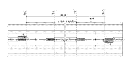
[0023] The safety channel 5 is located between the upward track 3 and the upward track 4, and is arranged under the rail platform 2. The safety channel 5 runs through the working wells 11 at both ends longitudinally (such as Figure 4 As shown), it is connected with the lower layer of the working shaft, and the air is blown by positive pressure from the fan room of the lower layer of the working shaft to form a smoke-proof passage.

[0024] Cable trays, equipment boxes, and water supply and drainage pipes are respec...


PUM


Abstract

The invention relates to a bottom independent evacuation safety passage structure for a single-hole double-track magnetic levitation tunnel, and the bottom independent evacuation safety passage structure comprises a safety passage and an escape platform, wherein the safety passage is positioned between an uplink track and the upward track and arranged below a track bearing table, and the escape platform is positioned between the upward track and the upward track and arranged on the track bearing table. The escape platform is connected with the safety passage through an evacuation staircase. Once fire or other accidents occurs/occur in upper-layer space in the tunnel, the safety passage can play roles in rescue and evacuation, and fire protection and rescue staff can also arrive at a fire accident scene through the safety passage. The bottom independent evacuation safety passage structure can also be used as an overhaul passage under normal situations and failures.

Description


Claims


Application Information

Patent Timeline
23 Nov 2011
Publication
CN102251802A