
Spinning die for spinning box

A technology of spinning die head and spinning box, which is applied in the direction of spinneret assembly, textiles and paper making, etc. It can solve the problems of pipeline blockage, large deviation of inner diameter of pipelines at the same level, and carbonization of materials, etc., and achieves convenient processing and installation, and export The effect of uniform distribution and easy processing size

Inactive Publication Date: 2011-11-30
CHANGZHOU HUIMING PRECISION MACHINERY
View PDF5 Cites 5 Cited by
  • Summary
  • Abstract
  • Description
  • Claims
  • Application Information

AI Technical Summary

Problems solved by technology

[0003] The disadvantage of the above-mentioned prior art is that in production, the problem of pipeline blockage is often encountered, and the position of the blockage is generally at the corner of the pipeline
If the treatment is not timely, it will lead to carbonization of the material in the entire distribution pipeline, which will cause great difficulties in the dredging of the pipeline, and even cause the entire spinning box to be scrapped.
Secondly, the distribution uniformity of the melt is poor. The reasons are: 1. Due to the existing pipeline processing technology, the inner diameter deviation of the same level pipeline is relatively large, and it is impossible to ensure that the discharge volume of each pipeline is highly uniform.
2. There is a problem that it is difficult to achieve uniformity in the distribution of the pipelines used

Method used


Image

  • Spinning die for spinning box
  • Spinning die for spinning box
  • Spinning die for spinning box

Examples


Embodiment Construction

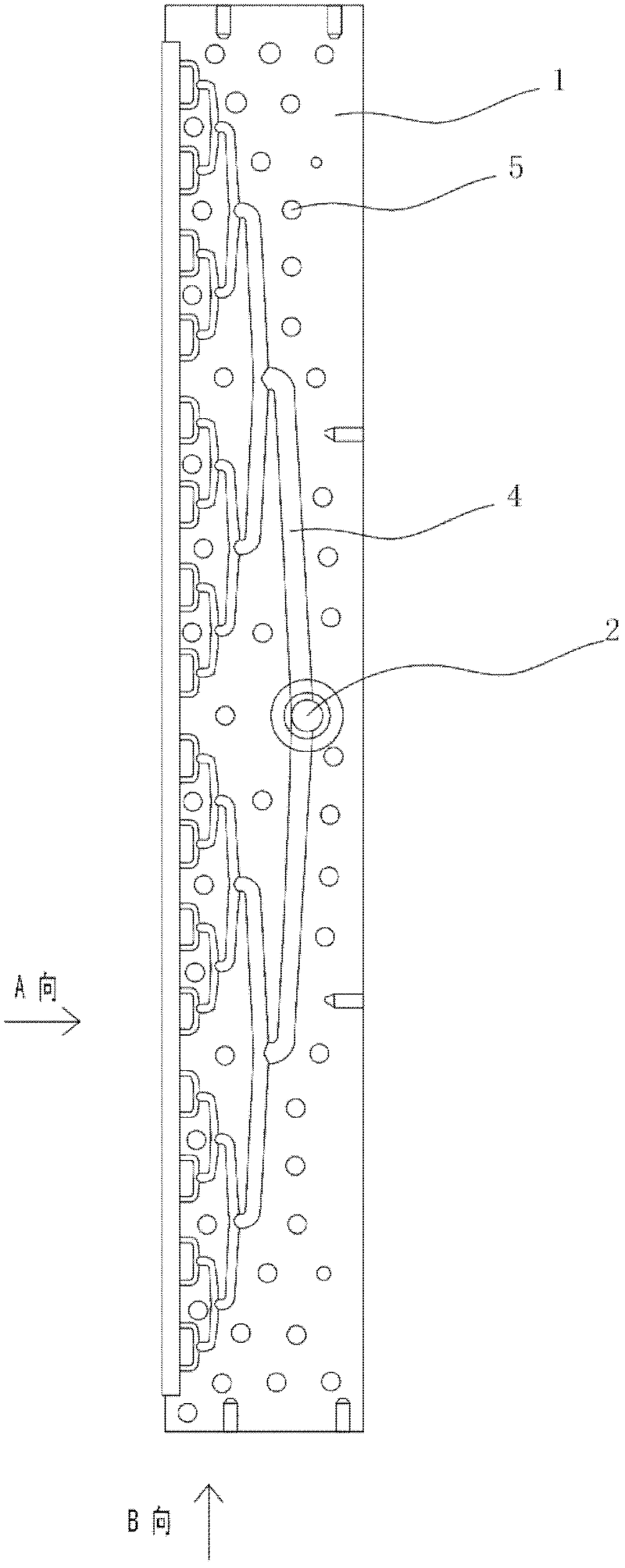
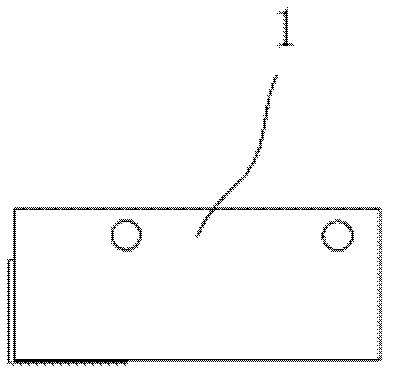
[0019] See Figure 1-5 , the spinning die for the spinning box of this embodiment comprises: a pair of die bodies 1 with symmetrical structures, and only a melt inlet 2 is provided at the central upper end of the inner wall of one of the die bodies 1, and a melt inlet 2 is provided on each die body. On the inner wall of the head body 1 and symmetrically distributed on both sides of the melt inlet 2, there are multi-stage conveying grooves 4 suitable for communicating with the melt inlet 2 during use, and the openings at both ends of the conveying grooves at each stage face downward. The outlet of the outlet is connected to the central part of the conveying trough of the next stage; the outlets of the conveying trough of the last stage are evenly distributed.

[0020] 200 mesh or 250 mesh filter screens 6 are arranged at the lower ends of the outlets at both ends of the final conveying tank in turn, and distribution plates 3 and spinneret plates 7 with through holes are evenly ...


PUM


Abstract

The invention relates to a spinning die head for a spinning box, which comprises: a pair of die heads with symmetrical structures, wherein a melt inlet is provided at the central upper end of the inner wall of one die head body, and on the inner wall of each die head body And on both sides of the melt inlet, there are multi-stage conveying troughs that are suitable for communicating with the melt inlet during use. The lower end of the outlet at both ends of the final conveying trough is provided with a filter screen, a distribution plate and a spinneret in turn. The inner wall of the die body is provided with a multi-stage conveying trough for conveying the melt, which has the advantages of convenient processing and installation, and is not easy to be blocked; even if a blockage occurs, it can be cleaned and dredged as long as the pair of die bodies are disassembled. It is not easy to scrap the die due to clogging; the processing size of the conveying groove is easy to control, the processing precision is high, and the distribution of each stage is divided into two, and the outlet is evenly distributed, which can ensure the uniform discharge of the melt.

Description

technical field [0001] The invention relates to the technical field of spinning boxes of spunbonded nonwoven fabric equipment, in particular to a spinning die head for spinning boxes. Background technique [0002] Chinese patent ZL200520047626.4 discloses a spinning box of spunbonded nonwoven equipment, which includes a melt inlet, several stages of conveying pipelines, each stage of conveying pipelines is provided with several pipeline outlets, and the outlets of each stage of conveying pipelines are in turn Set up the next-level conveying pipeline, the outlet filter screen of the bottom-level conveying pipeline, below the filter screen is a porous distribution plate with holes of different sizes, the melt will eventually flow out evenly from the holes of the porous distribution plate, and enter the nozzle silk board. The melt flows through the outlet of the pipeline set in several stages and passes through the porous distribution plate with holes of different sizes, so th...

Claims


Application Information

Patent Timeline
Patent Type & Authority Applications(China)
IPC IPC(8): D01D4/02D01D4/06
Inventor 唐惠奇
Owner CHANGZHOU HUIMING PRECISION MACHINERY
Learn More