Energy-saving type spinning die head for spinning box

A technology of spinning die head and spinning box, which is applied in the field of energy-saving spinning die head for spinning box, can solve the problems of slow heat conduction speed, low heat conduction efficiency, unfavorable energy saving, etc., and achieves easy blockage, high heat conduction efficiency, The effect of convenient processing and installation

Active Publication Date: 2013-11-27
CHANGZHOU HUIMING PRECISION MACHINERY
View PDF4 Cites 4 Cited by
  • Summary
  • Abstract
  • Description
  • Claims
  • Application Information

AI Technical Summary

Problems solved by technology

[0003] The disadvantages of the above-mentioned prior art are: the die head is heated by means of setting a heating plate on the side of the die head, resulting in a slow heat conduction rate (after starting up, the working temperature can only be reached after heating for more than 4 hours, and the mold can only be turned off after 4 hours of equilibrium. Head heat penetration) and low heat conduction efficiency, so the energy consumption is high, which is not conducive to energy saving

Method used


Image

  • Energy-saving type spinning die head for spinning box
  • Energy-saving type spinning die head for spinning box
  • Energy-saving type spinning die head for spinning box

Examples


Embodiment 1)

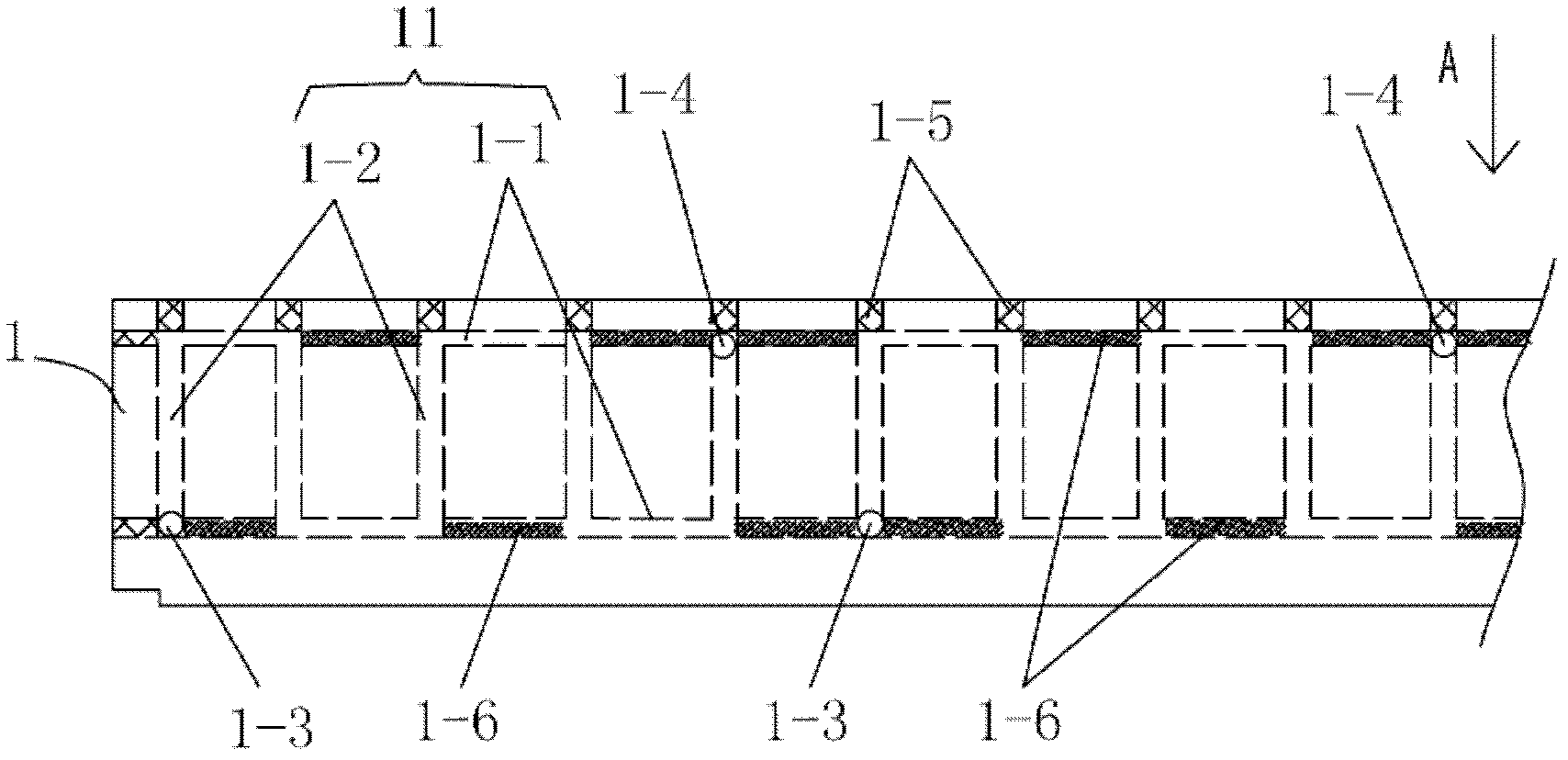
[0027] see Figure 1-4 , The energy-saving spinning die for the spinning box of this embodiment includes: a pair of symmetrical die head bodies 1, and a plurality of sections of square wave heat conduction oil channels 11 are distributed in the inner wall of the die head body 1; The liquid ports 1-3 and the liquid outlets 1-4 are respectively connected with the heat transfer oil inlet pipe 12 and the heat transfer oil outlet pipe 13.

[0028] The liquid inlet 1-3 is adjacent to the bottom of the die body 1, and the liquid outlet 1-4 of the heat conducting oil channel 11 is adjacent to the top of the die body 1.

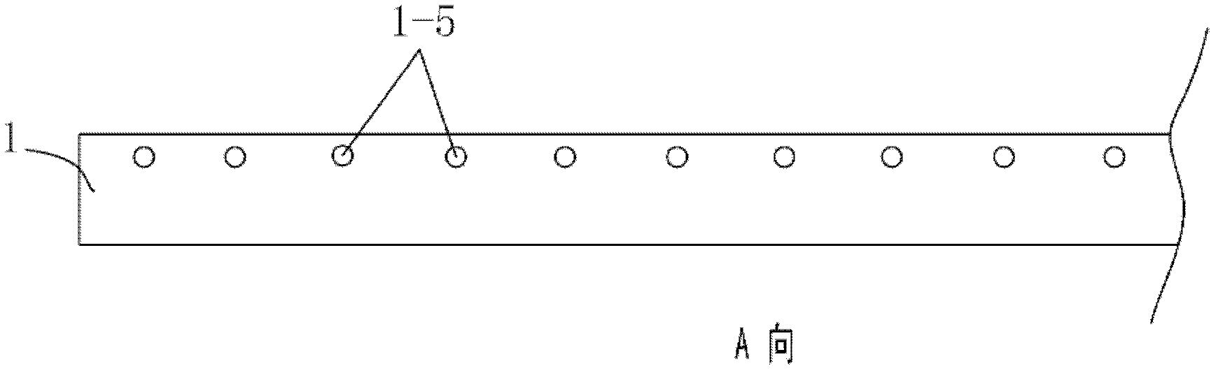
[0029] The heat transfer oil channel 11 includes: a pair of horizontal channels 1-1 distributed up and down, a plurality of longitudinal channels 1-2 connected between the pair of lateral channels 1-1; the process hole 1 of the longitudinal channel 1-2 -5 is on the top surface of the die body 1 and sealed during use, the process hole of the transverse channel 1-1 is on the...

Embodiment 2)

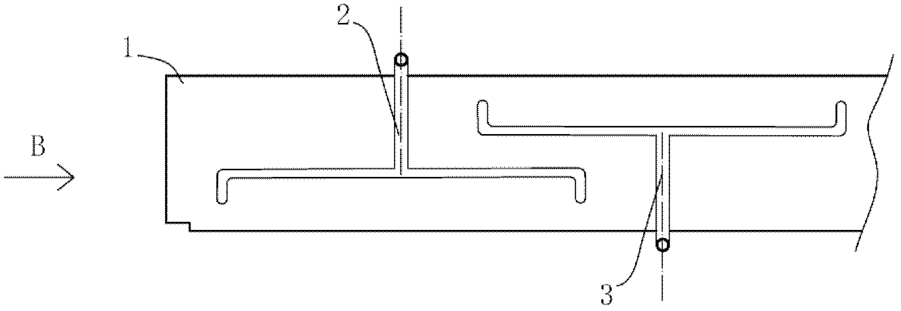
[0031] see Figure 5-9 On the basis of embodiment 1, the spinning die for spinning box of this embodiment has the following modification, namely: only one die body 1 is provided with a melt inlet 2 at the upper central end of the inner side wall of each die On the inner side wall of the head body 1 and on both sides of the melt inlet 2, there are symmetrically distributed multi-stage conveying troughs 4 suitable for communicating with the melt inlet 2 during use, and the openings at both ends of the conveying troughs at each level face The lower outlet is connected with the central part of the conveying trough of the next stage; the outlets of the final conveying trough are evenly distributed.

[0032] The lower ends of the outlets at both ends of the final conveying tank are successively provided with 200 mesh or 250 mesh filter screens 6, and a distribution plate 3 and a spinneret 7 with through holes are evenly distributed. The conveying groove 4 is a semi-circular groove or ...


PUM


Abstract

The invention relates to an energy-saving type spinning die head for a spinning box. The spinning die head comprises a pair of die head bodies with symmetrical structures, wherein multiple segments of square wave heat-conducting oil channels are distributed on the inner walls of the die head bodies; and the liquid inflow holes and liquid outflow holes of the square wave heat conducting oil channels are respectively connected with a heat conducting oil inflow pipe and a heat conducting oil outflow pipe. The spinning die head for the spinning box provided by the invention has the advantages that multiple segments of square wave heat-conducting oil channels are arranged on the inner walls of the die head bodies, so that the die head bodies are directly heated by heat conducting oil, thus the die head has the characteristics of higher heat conduction speed, high heat conduction efficiency and energy conservation; and shorter square wave heat conducting oil channels are suitable for ensuring that the flow rates at the heat conducting oil inflow holes and outflow holes are basically consistent, thus the integral temperature uniformity of the die head is ensured and the production quality of a product is improved.

Description

Technical field [0001] The invention relates to the technical field of a spinning box body of a spunbonded nonwoven fabric equipment, in particular to an energy-saving spinning die for the spinning box. Background technique [0002] Chinese patent ZL200520047626.4 discloses a spinning box of a spunbonded non-woven fabric equipment, which includes a melt inlet, several stages of conveying pipelines, each stage of conveying pipelines is provided with several pipeline outlets, and each stage of conveying pipeline outlets are in turn Set up the next-level conveying pipeline. Below the pipe outlet of the bottom-most conveying pipeline is a filter screen. Below the filter screen is a porous distribution plate with equally sized holes. The melt finally flows out evenly from the holes of the porous distribution plate and enters Spinneret. The melt flows through the outlets of the pipes arranged in several stages to pass through the porous distribution plate with holes of different sizes...

Claims


Application Information

Patent Timeline
Patent Type & Authority Patents(China)
IPC IPC(8): D01D4/00D01D4/06
Inventor 唐惠奇
Owner CHANGZHOU HUIMING PRECISION MACHINERY
Why Eureka
Try Eureka