
Super magnetostrictive material driven microdisplacement mechanism

A technology of micro-displacement mechanism and giant magnetostriction, applied in piezoelectric effect/electrostrictive or magnetostrictive motors, generators/motors, electrical components, etc., can solve high processing and assembly, poor interchangeability, Problems such as large loss of output force achieve the effect of easy processing and installation and good interchangeability

Inactive Publication Date: 2010-05-19
BEIJING UNIV OF CHEM TECH
View PDF7 Cites 8 Cited by
  • Summary
  • Abstract
  • Description
  • Claims
  • Application Information

AI Technical Summary

Problems solved by technology

It is a micro-displacement mechanism amplified by levers, the maximum magnification is only 5.1 times, and it cannot be used in occasions where the output of large displacement cannot meet the requirements
It uses a cantilever elastic beam as the amplification mechanism, which has a large loss of output force, and requires high processing and assembly, poor interchangeability, and the magnification factor cannot be adjusted.

Method used


Image

  • Super magnetostrictive material driven microdisplacement mechanism
  • Super magnetostrictive material driven microdisplacement mechanism
  • Super magnetostrictive material driven microdisplacement mechanism

Examples


Embodiment Construction

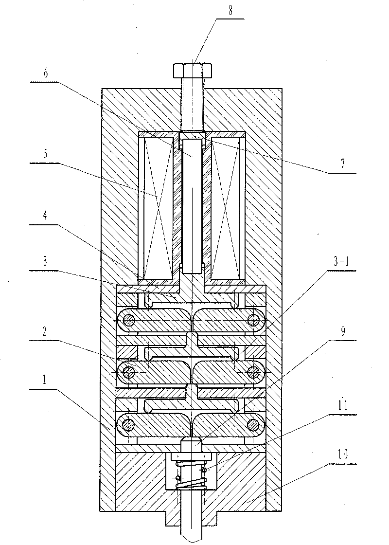
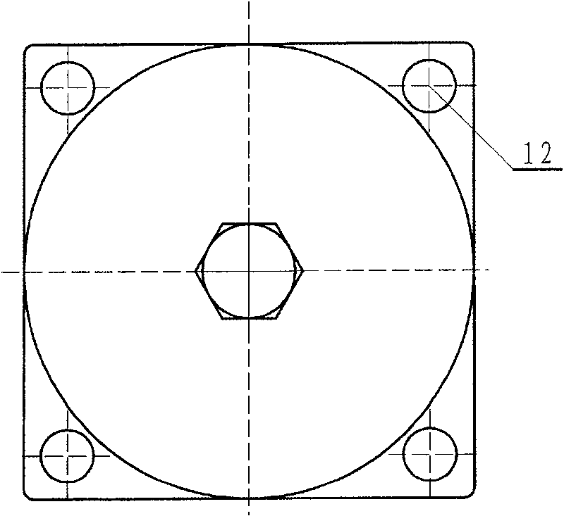
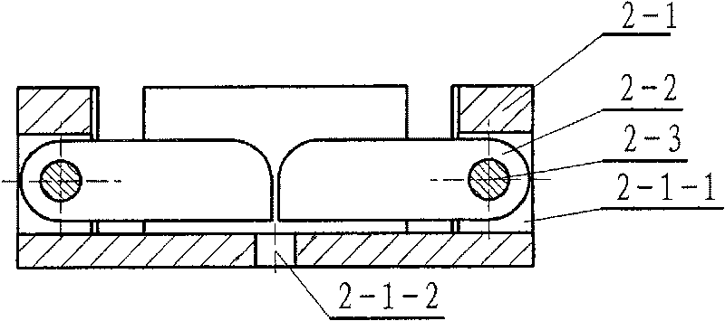
[0021] Micro-displacement mechanism of the present invention such as figure 1 and figure 2 As shown, its main structure includes: cylinder body (1), lever structure (2), transmission plate (3), lower limit ring (4), excitation coil (5), magnetostrictive rod (6), upper limit plate (7), adjusting screw (8), output rod (9), base (10) and return spring (11). An amplification mechanism is arranged between the magnetostrictive rod (6) and the output rod (9) inside the cylinder body (1). The amplification mechanism is composed of a lever member (2) and a transmission disc (3), and the transmission disc (3) is arranged on the lever member (2). Such as image 3 and Figure 4 As shown, the lever structure (2) is composed of a support (2-1), two symmetrical levers (2-2) and two pivot pins (2-3), and the positioning end of the lever (2-2) Be fixed in the through hole (2-1-1) of support (2-1) with axle pin (2-3), the upper side of the end of lever (2-2) has a fillet to facilitate lev...


PUM


Abstract

This invention relates to a micro-shift unit driven by a magnetostrictive material including: a tube, a lever structure, a driving disc, a lower spacing ring, an excitation coil, a magnetostrictive rod, an upper spacing disc, bolts, an output pole, a base and a reset spring, in which, an amplifying unit of 1-3 level is set between the magnetostrictive rod and the output pole composed of lever components and a driving disk, which selects combination of single level or multi-level amplifying unit and different amplifying multiples of single level lever to adjust the amplifying multiple of the micro-shift unit.

Description

technical field [0001] The invention relates to a micro-displacement mechanism driven by a giant magnetostrictive material, which is a mechanism for amplifying micro-displacement by utilizing the principle of leverage. Background technique [0002] The micro-displacement mechanism is mainly used in precision machine tools, precision measuring instruments, instruments and vehicle engine fuel injection systems. The driving mode of the micro-displacement mechanism is mainly multi-stage pole-connected electromagnets in series, piezoelectric ceramics, electromagnetic coils, etc. These micro-displacement mechanisms generally have low frequency response, small output force and displacement, and difficult to accurately control the output displacement. shortcoming. [0003] The micro-displacement mechanism driven by the giant magnetostrictive material is driven by the expansion and deformation of the giant magnetostrictive material under the action of the electromagnetic field of th...

Claims


Application Information

Patent Timeline
Patent Type & Authority Patents(China)
IPC IPC(8): H02N2/00H02N2/04
Inventor 谢鹏程杨卫民丁玉梅
Owner BEIJING UNIV OF CHEM TECH
Learn More