Energy-saving spinning die head for spinning box with fast heat conduction speed
A spinning die head and spinning box technology, which is applied to the field of energy-saving spinning dies for spinning boxes, can solve the problems of low thermal conductivity, slow thermal conductivity, unfavorable energy saving, etc., and achieves high thermal conductivity, not easy to block, The effect of convenient processing and installation
- Summary
- Abstract
- Description
- Claims
- Application Information
AI Technical Summary
Problems solved by technology
Method used
Image
Examples
Embodiment 1)
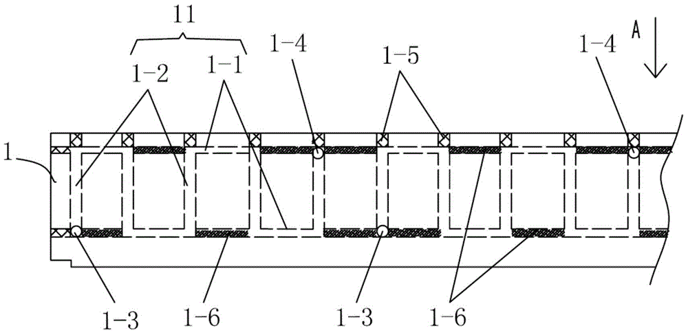
[0027] See Figure 1-4 , The energy-saving spinning die head for the spinning box of the present embodiment comprises: a pair of die head bodies 1 with symmetrical structure, and a plurality of sections of square wave heat transfer oil passages 11 are distributed in the die head body 1 inner wall; square wave heat transfer oil passages 11 The liquid inlet 1-3 and the liquid outlet 1-4 are connected to the heat transfer oil inlet pipe 12 and the heat transfer oil outlet pipe 13 respectively.
[0028] The liquid inlet 1 - 3 is adjacent to the bottom of the die head body 1 , and the liquid outlet 1 - 4 of the square wave heat transfer oil channel 11 is adjacent to the top of the die head body 1 .
[0029] The square wave heat transfer oil passage 11 includes: a pair of transverse passages 1-1 distributed up and down, a plurality of longitudinal passages 1-2 connected between the pair of transverse passages 1-1; the process of the longitudinal passages 1-2 The hole 1-5 is on the ...
Embodiment 2)
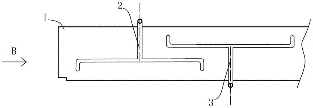
[0031] See Figure 5-9 , on the basis of Embodiment 1, the spinning die head of the spinning box of the present embodiment has the following modification, that is: only a melt inlet 2 is provided at the central upper end of the inner side wall of one die head body 1, and a melt inlet 2 is provided in each die head On the inner wall of the head body 1 and symmetrically distributed on both sides of the melt inlet 2, there are multi-stage conveying grooves 4 suitable for communicating with the melt inlet 2 during use, and the openings at both ends of the conveying grooves at each stage face The lower outlet is connected to the central part of the conveying trough of the next stage; the outlets of the conveying trough of the last stage are evenly distributed.
[0032] 200 mesh or 250 mesh filter screens 6 are arranged at the lower ends of the outlets at both ends of the final conveying tank in turn, and distribution plates 3 and spinneret plates 7 with through holes are evenly dis...
PUM
 Abstract
Description
Claims
Application Information
 - R&D
- Intellectual Property
- Life Sciences
- Materials
- Tech Scout
- Unparalleled Data Quality
- Higher Quality Content
- 60% Fewer Hallucinations
Browse by: Latest US Patents, China's latest patents, Technical Efficacy Thesaurus, Application Domain, Technology Topic, Popular Technical Reports.
© 2025 PatSnap. All rights reserved.Legal|Privacy policy|Modern Slavery Act Transparency Statement|Sitemap|About US| Contact US: help@patsnap.com


