
Rotating contact terminal component

A technology of contact assembly and contact arm, which is applied in the direction of contacts, electrical components, contact engagement, etc., can solve problems such as power distribution system paralysis, and achieve compact layout, good electrical contact, and best instantaneous current withstand capacity Effect

Inactive Publication Date: 2014-12-31
SIEMENS AG
View PDF5 Cites 0 Cited by
  • Summary
  • Abstract
  • Description
  • Claims
  • Application Information

AI Technical Summary

Problems solved by technology

This will bring down the entire power distribution system instead of just disconnecting the faulty part

Method used


Image

  • Rotating contact terminal component
  • Rotating contact terminal component
  • Rotating contact terminal component

Examples


Embodiment Construction

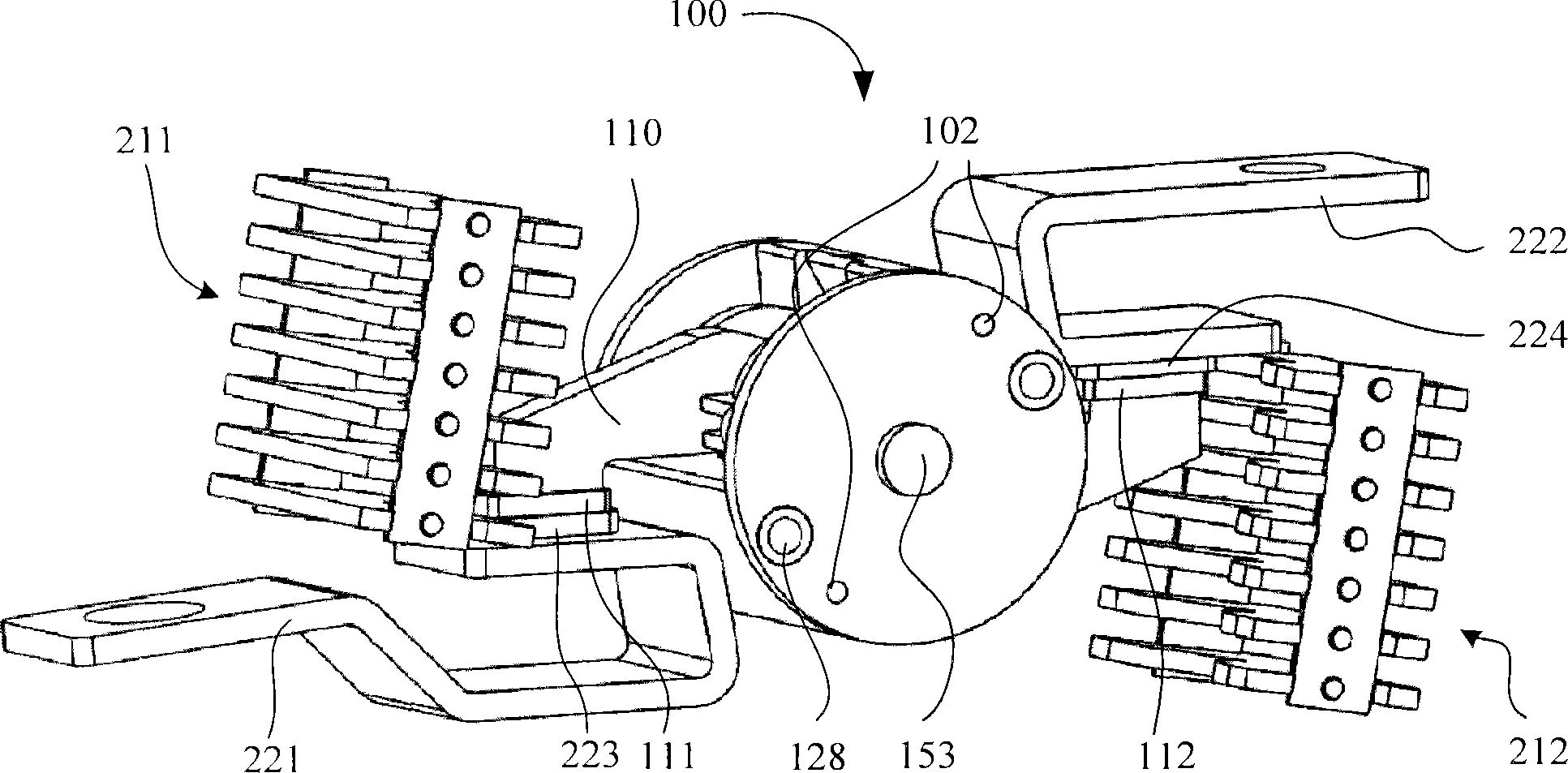
[0044] figure 2 A rotating contact assembly 100 according to an embodiment of the present invention is shown. The rotating contact assembly 100 is usually installed in figure 1 Inside the circuit breaker in the upstream circuit breaker USCB. In order to show more clearly, figure 2 The other parts of the circuit breaker are omitted. The rotating contact assembly 100 includes a contact arm 110 and a rotor 120, wherein the movable contact 111 and the movable contact 112 are respectively located at two ends of the contact arm 110. The first electrical conductor 221 (such as a power bar) and the second electrical conductor 222 (such as a load bar) are respectively located on two sides of the rotating contact assembly 100 and correspond to two ends of the contact arm 110 respectively. When the rotating contact assembly 100 is in figure 2 In the closed position shown, the static contact 223 is engaged with the movable contact 111, and the static contact 224 is engaged with the mov...


PUM


Abstract

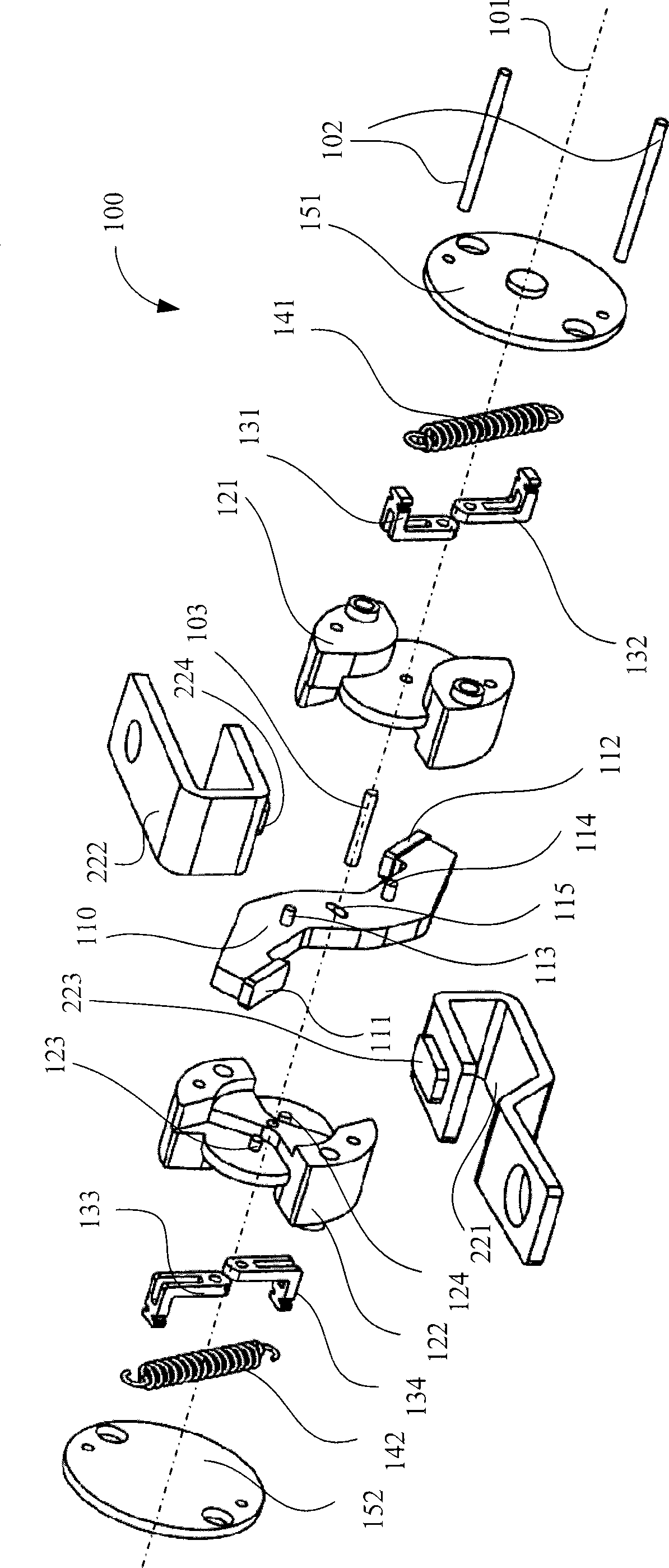
#CMT# # / CMT# The subassembly (100) has a shaft passing through a hole of a contact arm (110) to connect the contact arm, a rotor and a spring. A connecting arm comprises an end which is connected with the rotor in a pivoting manner and another end which is connected with an end of the spring. A guiding mechanism guides the contact arm to switch between a closing position and a breaking position, where spring force of the spring opens movable contacts (111, 112) of the contact arm and static contacts (223, 224) of electric conductors (221, 222) at the breaking position. #CMT#USE : # / CMT# Rotating contact subassembly for a circular breaker (claimed). #CMT#ADVANTAGE : # / CMT# The subassembly can be opened quickly under over current condition and can be re-closed after being opened under instantaneous over current condition while locking the breaking position reliably under strong over current condition. #CMT#DESCRIPTION OF DRAWINGS : # / CMT# The drawing shows a perspective view of a rotating contact subassembly. 100 : Rotating contact subassembly 110 : Contact arm 111, 112 : Movable contacts of contact arm 221, 222 : Electric conductors 223, 224 : Static contacts of contact arm.

Description

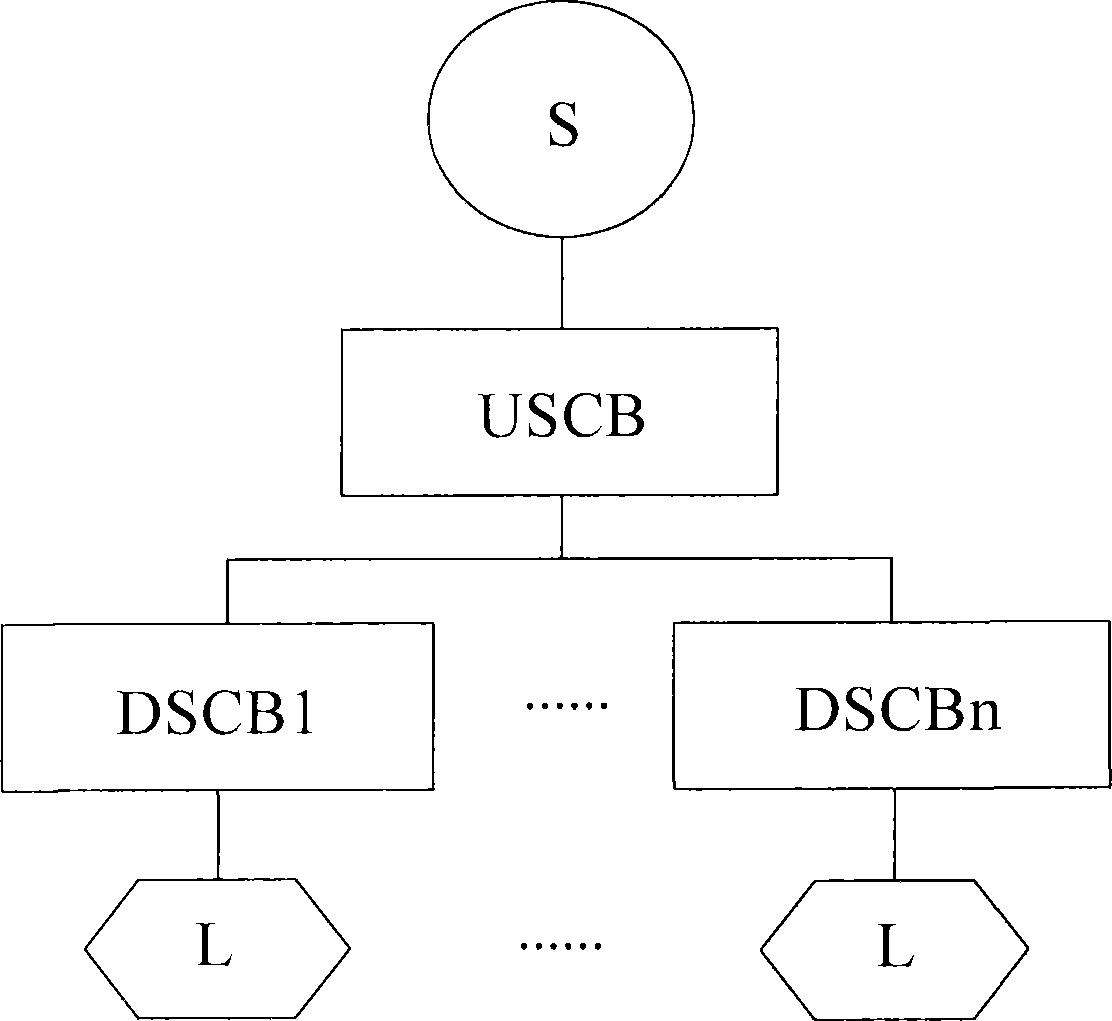
Technical field [0001] The invention relates to a rotating contact assembly, and more particularly to a current-limiting rotating contact assembly for a circuit breaker. In addition, the present invention also relates to a circuit breaker adopting the current-limiting rotating contact assembly. Background technique [0002] The circuit breaker is a key component of the power distribution system. figure 1 The power distribution system shown includes a power source S, an upstream circuit breaker USCB, at least one of 1 to n downstream circuit breakers DSCB, and a load L corresponding to the downstream circuit breaker DSCB. When there is an abnormal current in the circuit (for example, overcurrent, short circuit), these circuit breakers can automatically cut off the current flowing from the power source S to the load L to protect the circuit and components on the load L side. These circuit breakers usually have a trip unit for detecting the abnormal current and an operating mechani...

Claims


Application Information

Patent Timeline
Patent Type & Authority Patents(China)
IPC IPC(8): H01H73/04H01H1/22
CPCH01H77/104H01H73/045H01H1/205
Inventor 张先刚卓越
Owner SIEMENS AG
Learn More