A rotary contact assembly

A technology of contact assembly and contact arm, which is applied in the direction of contacts, electrical components, contact engagement, etc., can solve problems such as power distribution system paralysis, and achieve compact layout, good instantaneous current tolerance, and easy reset operation Effect

Inactive Publication Date: 2011-11-30
SIEMENS AG
View PDF5 Cites 8 Cited by
  • Summary
  • Abstract
  • Description
  • Claims
  • Application Information

AI Technical Summary

Problems solved by technology

This will bring down the entire power distribution system instead of just disconnecting the faulty part

Method used


Image

  • A rotary contact assembly
  • A rotary contact assembly
  • A rotary contact assembly

Examples


Embodiment Construction

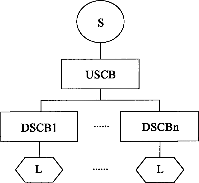
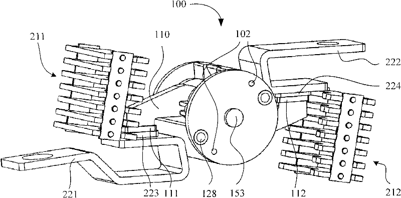
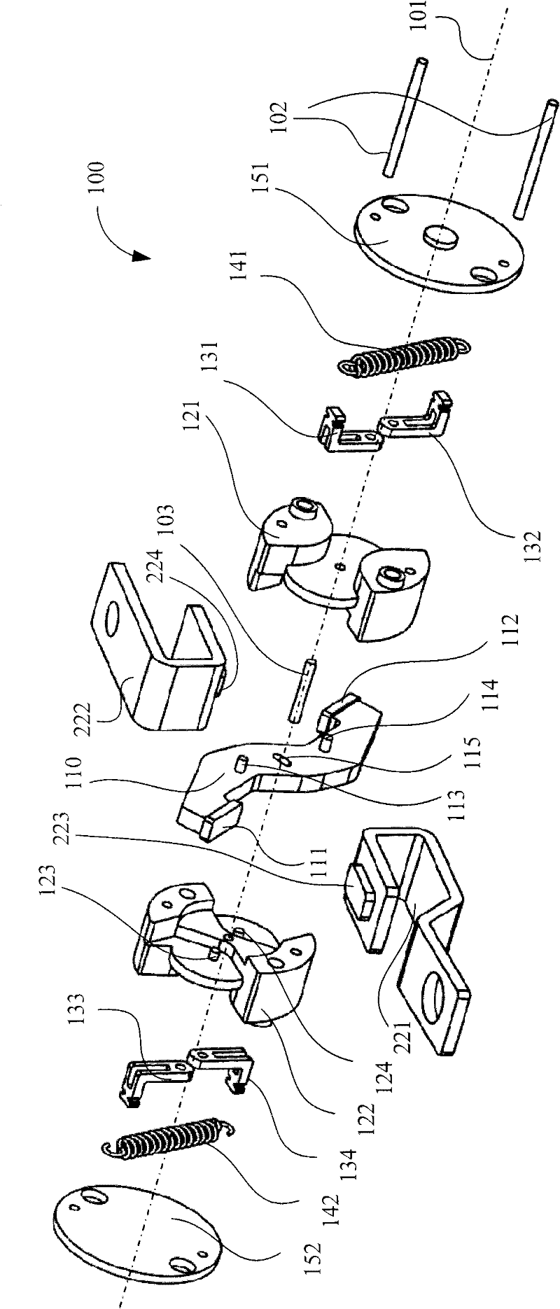
[0044] figure 2 A rotary contact assembly 100 according to one embodiment of the invention is shown. The rotary contact assembly 100 is usually installed in a figure 1 Inside the circuit breaker of the upstream circuit breaker USCB. To show more clearly, figure 2 Other parts of the circuit breaker are omitted. The rotary contact assembly 100 includes a contact arm 110 and a rotor 120 , wherein the movable contact 111 and the movable contact 112 are respectively located at two ends of the contact arm 110 . The first electrical conductor 221 (such as a power bar) and the second electrical conductor 222 (such as a load bar) are respectively located on two sides of the rotary contact assembly 100 and correspond to two ends of the contact arm 110 . When the rotary contact assembly 100 is in figure 2 In the closed position shown, the fixed contact 223 is engaged with the movable contact 111 and the fixed contact 224 is engaged with the movable contact 112, thus establishing ...


PUM


Abstract

The invention relates to a rotating contact terminal component which comprises a rotor, a contact arm, a shaft, a spring, a connecting arm and a guiding mechanism, wherein the contact arm has a hole; the shaft penetrates through the hole, so as to rotatably connect the contact arm with the rotor; one end of the connecting arm is pivoted with the rotor while the other end is connected to one end of the spring; the guiding mechanism is used for guiding the contact arm to switch between a closing position and an opening position; and under the action of an elastic force of the spring, a torque generated by the contact arm is used for closing a moving contact of the contact arm and a fixed contact of an electric conductor at the closing position and is used for opening the moving contact of the contact arm and the fixed contact of the electric conductor at the opening position. The rotating contact terminal component can be quickly opened at overflowing state, can be reclosed after being opened at instant overflowing state and can be reliably locked at the opening position at strong overflowing state.

Description

technical field [0001] The present invention relates to a rotary contact assembly, and more particularly to a current limiting rotary contact assembly for a circuit breaker. In addition, the present invention also relates to a circuit breaker using the current limiting rotary contact assembly. Background technique [0002] Circuit breakers are critical components of power distribution systems. figure 1 The illustrated power distribution system includes a power source S, an upstream circuit breaker USCB, at least one of 1 to n downstream circuit breakers DSCB, and a load L corresponding to the downstream circuit breaker DSCB. When there is an abnormal current (such as overcurrent, short circuit) in the circuit, these circuit breakers can automatically cut off the current flowing from the power source S to the load L to protect the circuit and components on the load L side. These circuit breakers generally have a trip unit for detecting the abnormal current and an operating ...

Claims


Application Information

Patent Timeline
Patent Type & Authority Applications(China)
IPC IPC(8): H01H73/04H01H1/22
CPCH01H1/205H01H77/104H01H73/045
Inventor 张先刚卓越
Owner SIEMENS AG
Why Eureka
Try Eureka