Eureka AIR delivers breakthrough ideas for toughest innovation challenges, trusted by R&D personnel around the world.

A submersible pump mounting frame for a pumpable water tank

A technology for submersible pumps and mounting frames, which is applied in the direction of machines/brackets, supporting machines, mechanical equipment, etc. It can solve problems such as inflexible design, water tanks that cannot be shallow, and swing rods that cannot maintain a horizontal position, achieving the effect of flexible internal design

Inactive Publication Date: 2011-12-14
GREE ELECTRIC APPLIANCES ZHONGSHAN SMALL HOUSEHOLD APPLIANCES MFG +1
View PDF3 Cites 1 Cited by
  • Summary
  • Abstract
  • Description
  • Claims
  • Application Information

AI Technical Summary

Problems solved by technology

In order to have a better use effect, the water pump is placed horizontally at the bottom of the water tank. The depth of the water tank should be consistent with the length of the pendulum extending into the water tank. In order to make the structure compact without increasing the volume of the cooling fan, the support seat is just above the water tank. , in this case, according to the structure provided by the specific implementation of the above-mentioned patent, the depth of the water tank cannot be shallow, because the water tank is shallow, the swing rod will be short, and then the water pump will be affected by the swing when the swing rod rises. The support seat is restricted, so that the pendulum cannot maintain a horizontal position, and the water tank cannot enter and exit
[0003] Therefore, the submersible pump mounting frame of the above structure makes the cooling fan or the equipment that needs to use the submersible pump mounting frame less flexible in design

Method used


Image

  • A submersible pump mounting frame for a pumpable water tank
  • A submersible pump mounting frame for a pumpable water tank
  • A submersible pump mounting frame for a pumpable water tank

Examples


Embodiment Construction

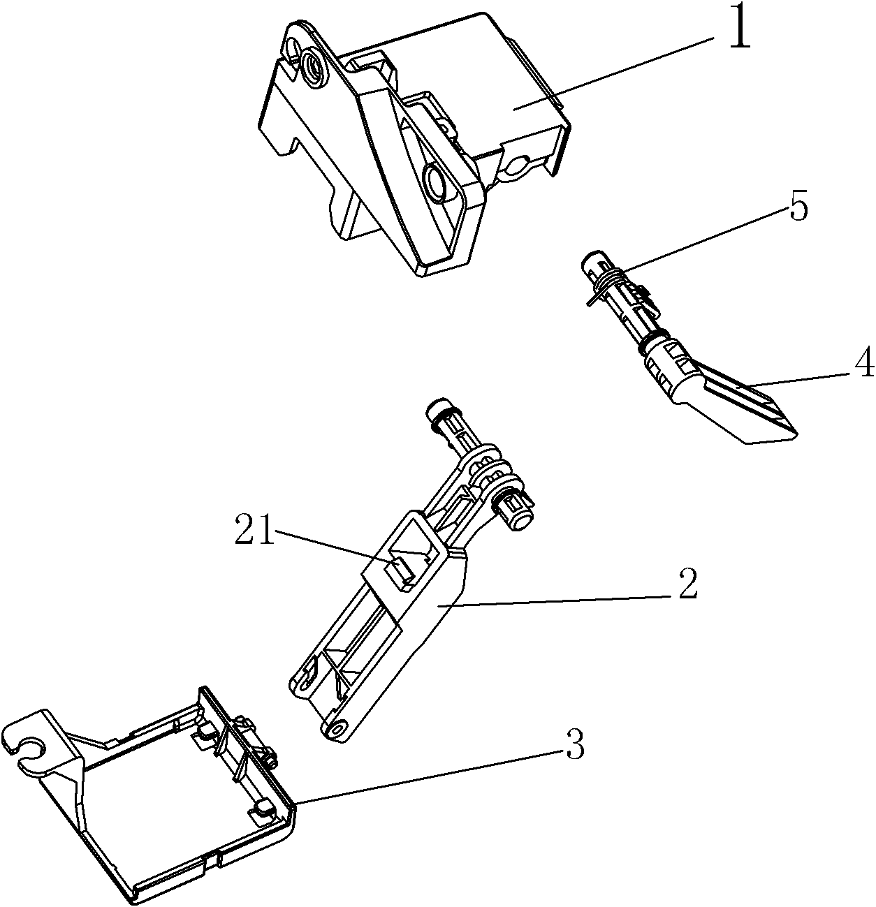
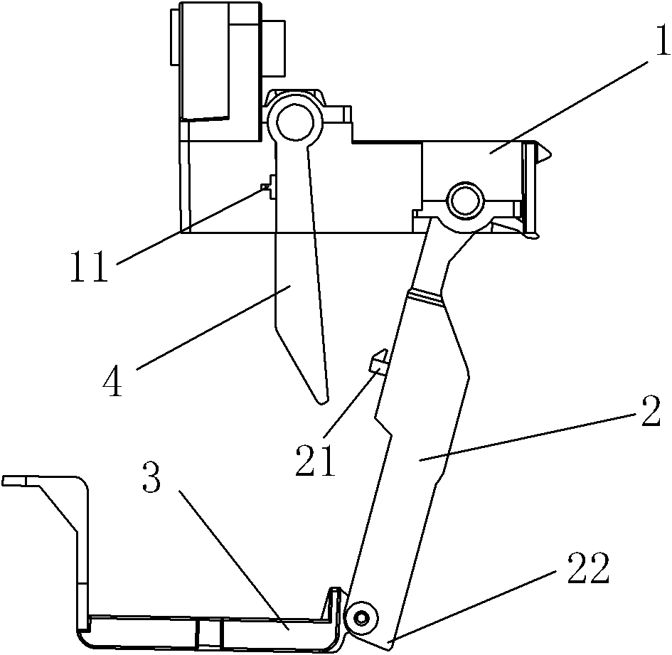
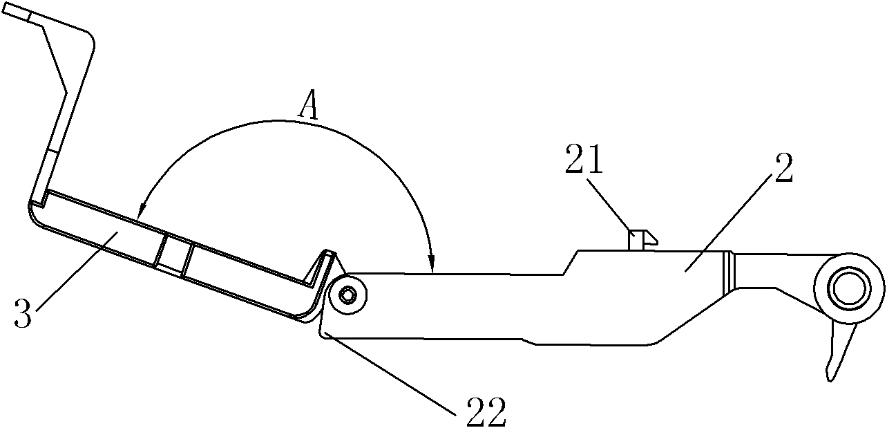
[0027] like Figure 1 to Figure 3 As shown, a submersible pump mounting bracket for a pumpable water tank provided by the present invention includes a support base 1, a swing bar 2 provided with a first hook 21, a mounting base 3 for installing a submersible pump, and an adjustment Switch; one end of the swing rod 2 is rotatably connected to the support base 1, and the other end of the swing rod 2 is rotatably connected to the mounting base 3; the swing rod 2 is provided with a device for limiting the angle A between the mounting base 3 and the swing rod 2 to not exceed 180° In this embodiment, the angle A between the mounting base 3 and the swing rod 2 is at most 180°; the mounting base 3 is provided with a horizontal installation space for a submersible pump horizontal installation position (of course, the horizontal installation space also It can be set to be more than one submersible pump horizontal installation position to make the submersible pump flexible placement).

...


PUM


Abstract

The invention relates to a submersible pump installation frame for a pumpable water tank, which includes a support base and a swing rod, and one end of the swing rod is rotatably arranged on the support base; The installation seat of the submersible pump is connected to the other end of the swing rod in rotation. Because the installation seat and the swing rod are designed to be connected in rotation, the water tank used can make the submersible pump be horizontally placed under the water tank as long as the water tank used satisfies the condition that "the length of the swing rod extending into the water tank is greater than the depth of the water tank". Therefore, the present invention can be applied The water tanks of various specifications are beneficial to use the equipment of the present invention to be flexible in design.

Description

【Technical field】 [0001] The invention relates to a submersible pump mounting frame, in particular to a submersible pump mounting frame for placing the submersible pump inside a pumpable water tank. 【Background technique】 [0002] At present, most of the home appliances involved in humidification on the market use submersible pumps as water circulation power equipment. The submersible pumps need to be placed in the water tank to work. However, due to the influence of the installation position of the submersible pump, the water tank cannot be drawn out or only half of it can be drawn out, which is very uncomfortable. It is convenient for the user to add water to the water tank and clean the inside of the water tank. At present, the utility model patent No. 200920291940.5 filed by the applicant in China discloses a cooling fan pumpable water tank structure, which includes a water tank placed in the cooling fan, a submersible pump placed in the water tank And a submersible pum...

Claims


Application Information

Patent Timeline
IPC IPC(8): F16M13/02F16M11/06
Inventor 汪安理何志威李曙光
Owner GREE ELECTRIC APPLIANCES ZHONGSHAN SMALL HOUSEHOLD APPLIANCES MFG
Why Eureka
Eureka Blog
Learn More